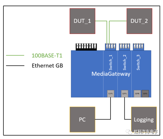
這個文章將會展示如何去紀錄兩個設備(例如ECU)之間的車載乙太網通信,接線圖如下。
DUT_1和DUT_2之間的鏈路必須被分成兩段並通過Media Gateway重新連接。中間的RJ-45端口用於紀錄這兩個DUT之間的通訊,最左側的RJ-45端口用於配置Media Gateway。
我們建議使用雙VLAN標記的功能,尤其是當紀錄的網絡中已經有使用單VLAN標記
請參考Media Gateway的配置步驟:
1.這裡我們從Media Gateway的默認配置開始。您可以通過設備上的按鈕將設備恢復成初始設置,但是請注意您現有所有的配置都將被重置。
2.按照圖片連接所有設備。配置設備時需要一台PC。
3.不要忘記為Media Gateway供電,也不要忘記配置您的網絡適配器和Media Gateway在同一網段。
4.打開您PC上的瀏覽器,輸入默認的IP地址:192.168.0.49。
5.選擇Switch Status選項卡。
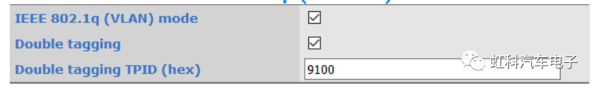
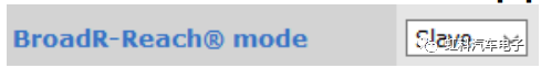
6.激活 IEEE 802.1q (VLAN) mode和Double tagging。 (VLAN模式和雙VLAN標記)
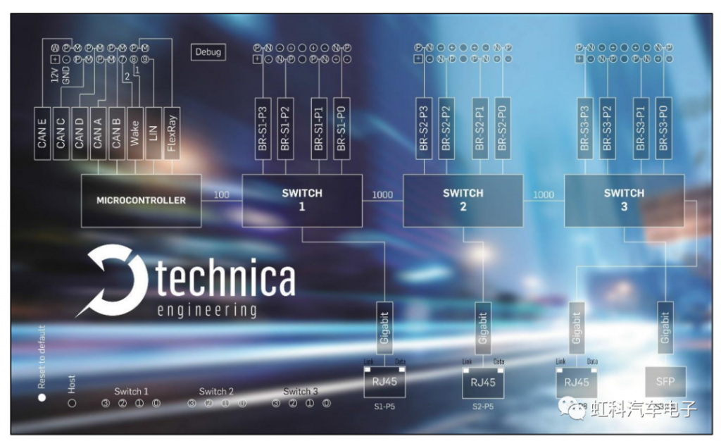
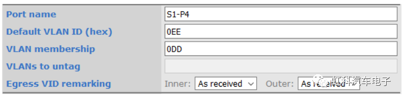
7.轉到端口 (S1-) P4 (CPU)。
8.設置default VLAN ID的值,例如0xEE。
現在,所有從Switch_1的S1-P4端口傳入的幀,如果沒有VLAN標記,都會被打上VLAN ID的標記。因此,由於微控制器不屬於Switch_1的一部分,來自微控制器的幀將會被打上這個VLAN ID的標記(內層VLAN和外層VLAN)。
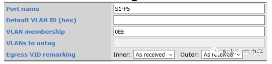
9.轉到端口 S1-P5
10.將VLAN membership設置為與端口P4 (CPU)的default VLAN ID相同,現在在S1-P4端口傳入的幀可以從Switch_1的這個端口離開。
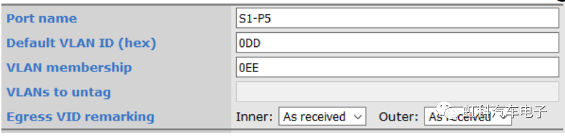
11.對另一個方向做類似的配置,例如選用0xDD作為這個VLAN ID。
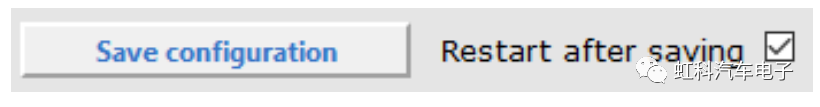
12.保存一下
13.這樣我們就定義了配置端口是通過S1-P5
14.現在對DUT_1和DUT_2之間的連接執行相同的操作
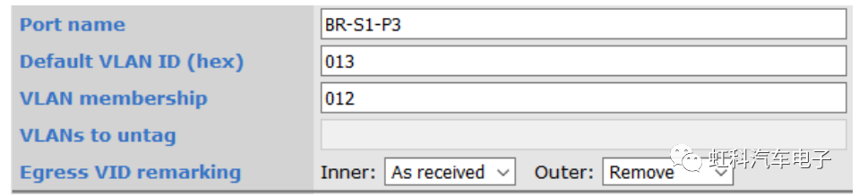
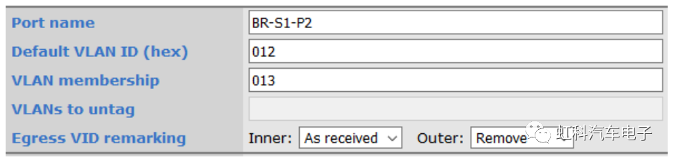
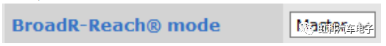
15.修改這兩個端口的主從模式。保證S1-P3端口的配置和DUT_1設備相反,同樣,S1-P2端口和DUT_2相反。
16.此時DUT_1和DUT_2之間的連接已建立,如果您現在進行保存並重新啟動Media Gateway,兩個DUT應該能夠相互通訊。
17.要在端口S2-P5上記錄數據,必須激活端口S1-P8和S2-P5上的鏡像功能。
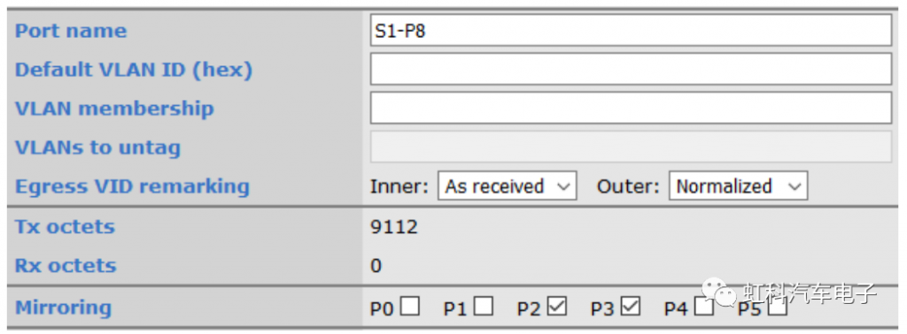
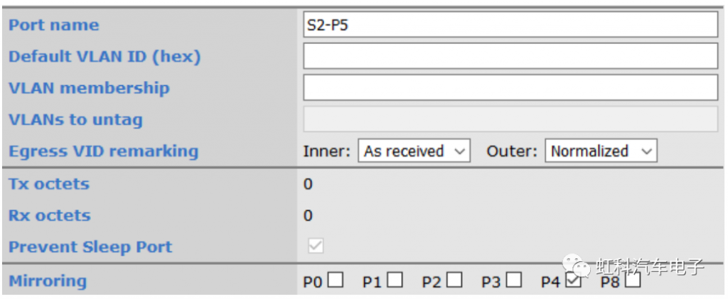
18.出端口VID(外部VLAN)的重新標記已標準化。這意味著您可以在記錄的數據上找到配置好的VLAN標記,以便通過端口輕鬆過濾數據。
由於使用鏡像功能,這裡不需要設置VLAN membership。
這個配置不涉及內部VLAN ID。原始數據是否具有單VLAN標記不會影響配置(出端口VID標記為“已接收”)
19.保存即可完成配置