CAN bus has been widely used in automotive and industrial fields due to its advantages of reliability, real-time, economy, and flexibility, and has been gradually popularized in applications such as battery storage, medical devices, and intelligent buildings. With the application of CAN bus in more and more fields, the demand for CAN bus testing is also increasing.
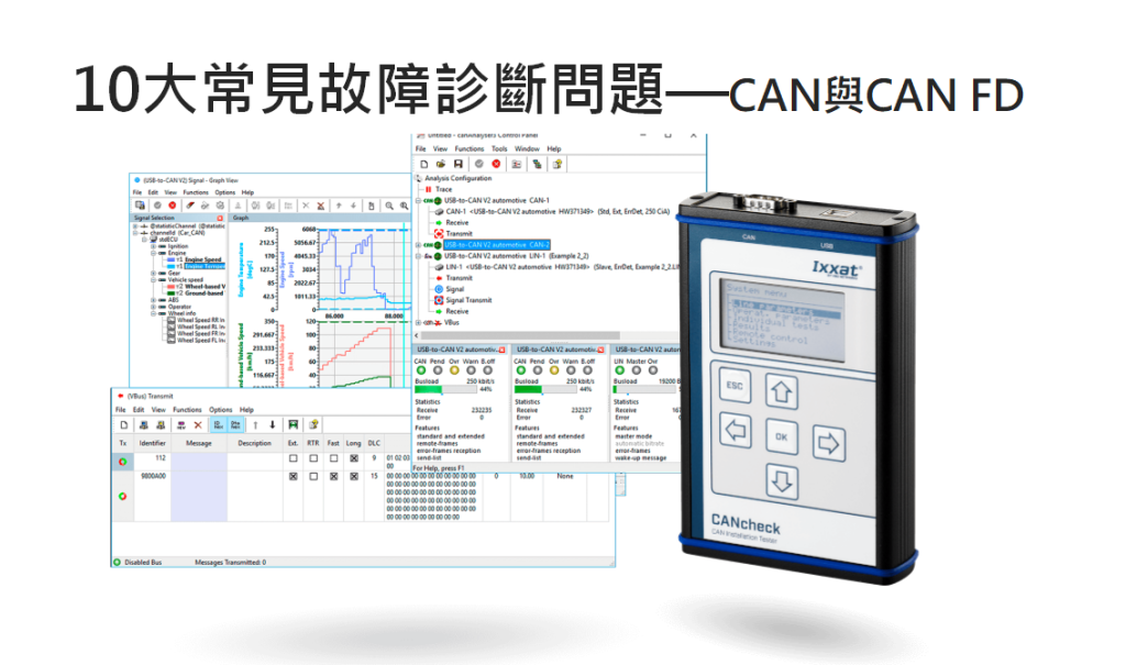
This article summarizes 10 normal testing process often encountered in some typical problems, and give solutions to help you more smoothly complete the test.
Article Outline
01 Broken Lines
02 Cable type error: non-CAN cable
03 Improper wiring
04 There is only 1 node on the network that is communicating properly.
05 CAN line is too long
06 High bus load factor
07 Terminal resistance error
08 Baud rate error
09 Communication conflicts caused by the same ID
10 Same baud rate but different clock frequencies.
01 Broken Lines
If the cable is damaged, CAN communication cannot continue.
[Solution]
1、If it is obvious that the cable is damagedJust change the wires.
2, the appearance can not be seen, you can use the broken circuit tester to check each pin, to determine the cable damage, replace the line.
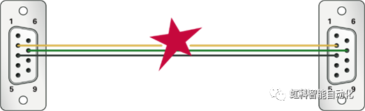
02 Cable type error: non-CAN cable
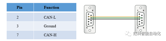
It is possible to have a cable in the field that appears to be used for CAN but is not actually a CAN cable and does not meet the standard definition. Most common products utilize the DSub9 connector, which meets the specifications of the CiA® 303-1 pin definition. Other connectors such as RJ45 are also possible.
The following table defines the pinout of DB9 CAN.
[Solution]
Check the pin assignments of the cables and replace the cables if they are not up to standard; if they are up to standard, check other areas.
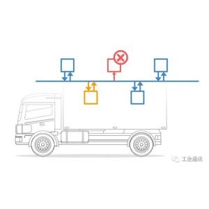
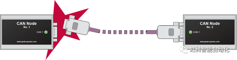
03 Improper wiring
When there are multiple nodes in a CAN network and multiple plugs need to be connected, it is very likely that theConnection ErrorThe following is an example of a CAN communication error. CAN communication is not possible or sporadic errors occur.
[Solution]
1、Check if all the cables are correctly plugged in.
2、Check if all the connectors match the pins.
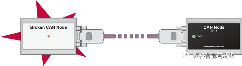
04 網路There is only one node with normal communication on the
A properly functioning CAN network has at least two or more CAN nodes. If only one CAN node is functioning properly, its error state goes to a passive error because it does not receive an acknowledgement from the other party after sending data.
[Solution]
You can monitor the error status of the node with an analyzer:
- Bus Light: When there are more than 96 errors, it goes to ”error active”.”
- Bus Heavy: more than 127 errors, went to ”error passive”.”
- Bus Off: more than 255 errors, go to ”bus off”.”
Attention:If there is only one functioning CAN node and it sends a CAN message, the message is retransmitted very quickly until it receives an acknowledgement from another node or enters a passive error state.
This information can be obtained through CANking or CANeasy.Tap me to learn about CAN analysis tools
05 CAN lines are too long
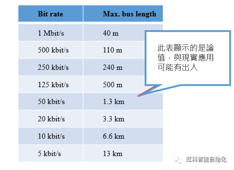
A baud rate of 1 Mbit/s cannot exceed 40 m (theoretical) in a perfect cabling system. The maximum cable length also depends on the transceiver used.
For CAN FD, the baud rate is also dependent on the cable length, and even though CAN FD has a higher baud rate, if the total cable length exceeds 40 meters, the CAN data will be invalidated because the ACK bits arrive too late.
[Solution]
Shorten the length of cables according to the actual situation
06 High bus loading rate
High bus loads can cause transmission failures. This is usually caused by sending too much data, especially if the baud rate and cycle time are high. Alternatively, an error in a piece of CAN data, which the CAN controller keeps trying to retransmit, can cause the bus load to increase.
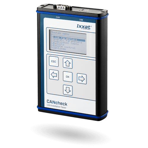
Diagnostic method: Use Ixxat CANcheck to diagnose the bus loading rate.
[Solution]
1. Reduction of information
2、 Extend the data sending cycle
3. Increase in bus baud rate
4、 If CAN2.0 is used, CAN FD can be considered later.
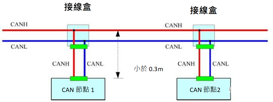
07 Terminal resistance error
The high-speed CAN bus (ISO 11898-2) must have a 120 Ω terminating resistor at each end of the CAN cable (between CAN_L and CAN_H). This helps to minimize signal reflection from the cable and ensures proper operation of the CAN transceiver.
[Solution]
1. Use CANcheck to measure the terminal resistance between CAN_L and CAN_H.
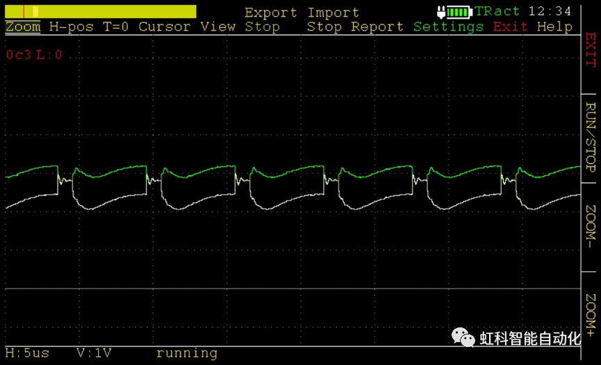
2、Experienced users can use CANcheck's oscilloscope to evaluate the terminal resistance (see the flank ringing, etc.).
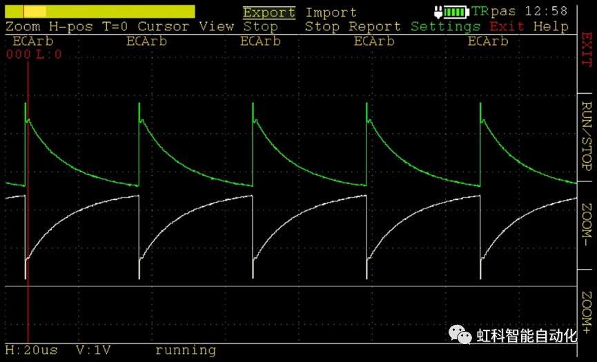
Below we will look at the waveform characteristics for different terminal resistances:
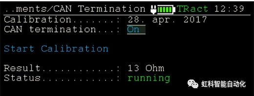
① Terminal resistance case 1: Over termination
Cause of overload: Too much terminal resistance access
Normal parallel connection of two 120 ohm terminal resistors should be about 60 ohms, but the following picture shows 13 ohms, which causes CAN waveform distortion.
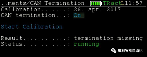
② Terminal Resistor Condition 2: Terminal Resistor Connection Too Low or Missing
Normal parallel connection of two 120 ohm terminal resistors should be about 60 ohms, as shown below, it is a loss, resulting in CAN waveform distortion.
08 Baud rate error
The baud rate of each node on the same network should be consistent. If it is not consistent, the node will enter the bus off error state and affect the communication of other nodes.
[Solution]
Use Ixxat CANcheck to check the baud rate of the CAN/CAN FD network.
09 Communication conflicts caused by the same ID
In a CAN network, it should be guaranteed that the data IDs of each node are different; if two data IDs are found to be the same, there is no way to arbitrate which data has higher priority, and each conflict will cause the error counter to add 1.
[Solution]
You can use the Error frames of Ixxat CANcheck to see the number of error frames per unit of time, or you can use the canAnalyser software to monitor online to find out which CAN data are in conflict.
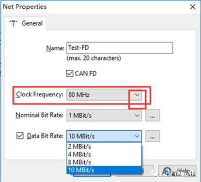
10 Same baud rate but different clock frequency
This is mainly for CAN FD network, in CAN FD network, the higher the baud rate, the closer to the physical limit. Therefore, it is not recommended to use different clock frequencies in the same network.
CiA is recommended to use a clock frequency of 40 or 80 MHz.
If there are any thoughts on this post, feel free to leave a comment and give us feedback!
If you are interested in our products, please click the button below to contact us.