Failure phenomenon
Fault Diagnostics
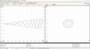
Using a fault detector, it was found that the fault code “P1339-00 FIRING RATE (IMPACT CATALYTIC CONVERTER): CATALYTIC CONVERTER DAMAGE, MISFIRE DETECTED IN CYLINDER 3” is stored in the engine control unit.Measure the crankshaft position sensor signal and cylinder 1 primary ignition signal waveforms using a Pico oscilloscope and perform frequency calculations on the crankshaft position sensor signal using the mathematical channel function.The crankshaft speed signal waveforms are obtained from the signal. The relevant waveforms measured when the engine is idling are shown in Fig. 1 below, and it can be found that the crankshaft speed fluctuates significantly; the local zoomed-in waveforms (Fig. 2) can be analyzed to show that theCylinder 1, Cylinder 3 and Cylinder 4 have a significant increase in crankshaft speed after ignition, while Cylinder 2 has a decrease in crankshaft speed instead of an increase after ignition, which indicates that Cylinder 2 has a complete misfire.。
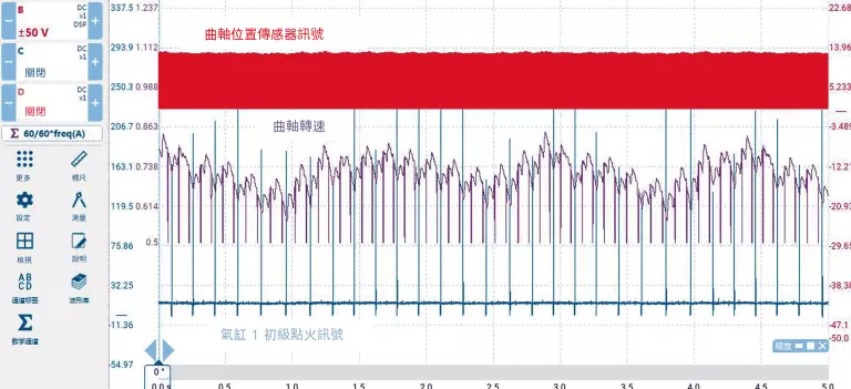
Fig. 1 Crankshaft position sensor signal and cylinder 1 primary ignition signal waveforms at engine idle.
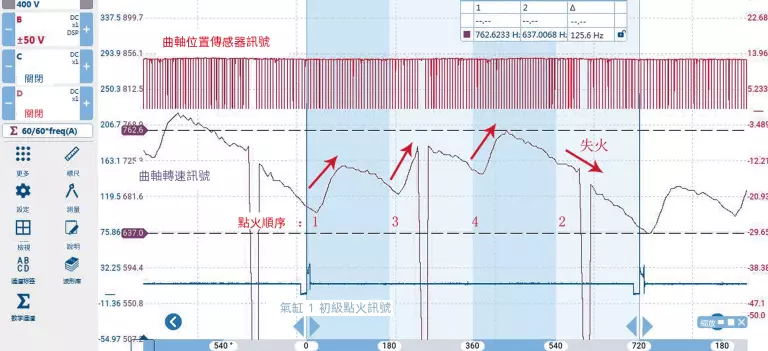
Fig. 2 Waveforms after regional amplification
Measurement of cylinder 2 primary ignition signal (Figure 3), again to verify the cylinder 2 ignition crankshaft speed does not rise but fall; amplify the cylinder 2 primary ignition signal (Figure 4), the waveform is normal, to rule out the possibility of ignition failure.
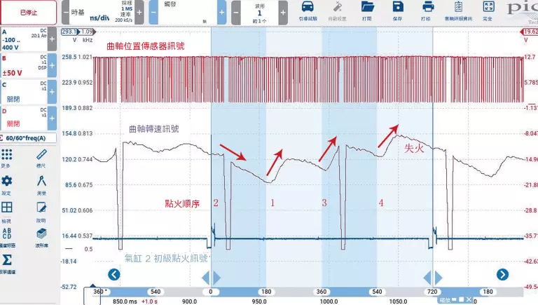
Fig. 3 Crankshaft position sensor signals and Cylinder 2 primary points at engine idle.
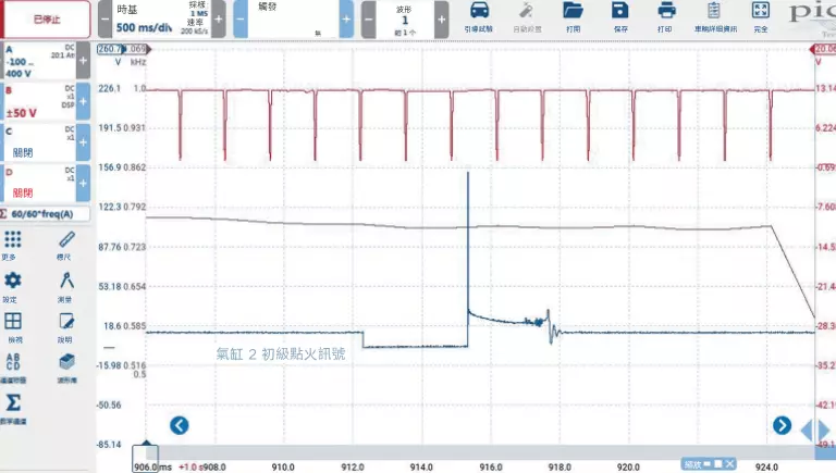
Fig. 4 Amplified Cylinder 2 Primary Ignition Signal Waveforms
Disconnect all ignition coil lead connectors and measure the waveforms associated with starting (Fig. 5).It is found that there is a significant increase in crankshaft speed after the ignition of cylinder 1, cylinder 3 and cylinder 4, while the increase in crankshaft speed after the ignition of cylinder 2 is very small.This means that the compressed gas exerts less thrust on the piston during the work stroke of cylinder 2, indirectly reflecting the lack of cylinder pressure in cylinder 2.
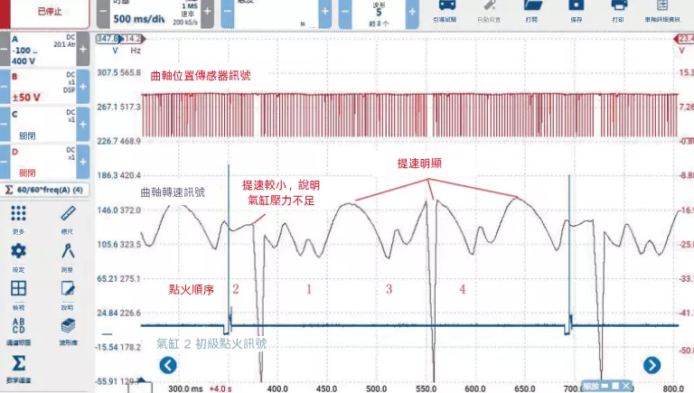
Fig. 5 Crankshaft Position Sensor Signal and Cylinder 2 Primary Ignition Signal Waveforms at Startup
Checked cylinder 2 with an endoscope and found that the exhaust valve was damaged ((Figure 6). It is inferred that the exhaust valve of cylinder 2 is damaged, resulting in insufficient cylinder pressure and cylinder misfire.

Figure 6 Damaged exhaust valve
fault resolution
Fault Summary
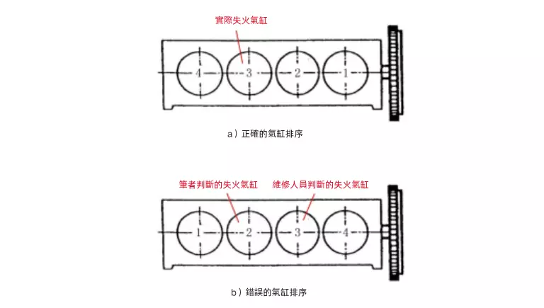
Fig. 7 Cylinder No.
Learn more about our products
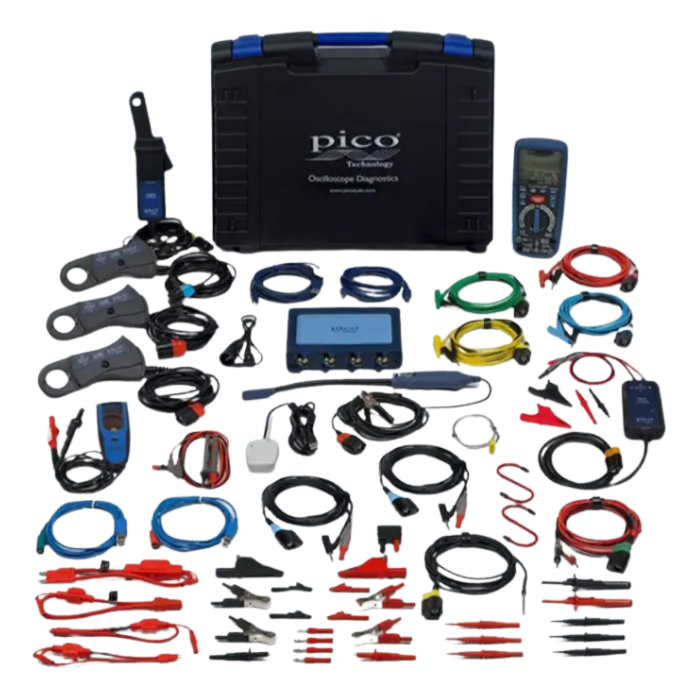
Pico4425A 4-Channel Motorized Vehicle Kit (EP070)
- Diagnostics for all vehicle types: Supports BEV, PHEV, MHEV, fuel cell and internal combustion engine (gasoline/diesel/LPG) systems.
- PicoBNC+™ Smart Connector: Plug and test, automatic recognition and software configuration, BNC compatible.
- EV specialized safety accessories: high pressure differential probes, insulation test cables and fuse extensions to ensure safe high pressure operation.
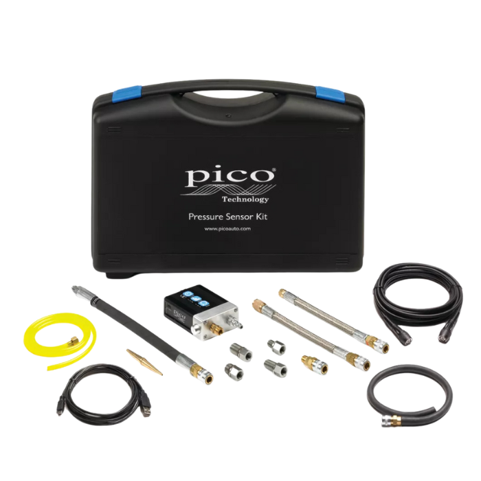
Acer Pico WPS500 Pressure Test Solution (EP076)
- Full Coverage Pressure Test: Cylinder, Crankcase, Intake & Exhaust, and Fuel Pressure in One Machine
- 100 µs ultra-fast response: up to 0.07 psi accuracy to accurately capture transients
- Three range switches: -15500 psi, -1550 psi, -5~5 psi for various scenes
If you are interested, you are welcome to follow us for more information about the article and contact us if you have any questions!