A simple intro to CAN errors
CAN bus error
In this series of articles, we will introduce you to the details of the CAN bus errorThe knowledge includes the basic concepts of CAN Bus Errors, types of CAN Bus Errors, CAN Error Frames, and CAN Node Error States, as well as generating and documenting CAN errors through practical application testing.
Back to previous article. CAN Bus Errors in Five Minutes - CAN Bus Errors and Error Frames (1)
Back to previous article. CAN Bus Errors in Five Minutes - CAN Bus Error Types (2)
Obviously, CAN error handling helps to remove the error message and enables the CAN node to re-transmit the error message. This ensures that short periods of localized interference (e.g. from noise) do not result in invalid/missing data. Instead, the transmitter will attempt to retransmit the message. If it wins arbitration (and there are no errors), the message is sent successfully.
But what if the error is caused by a system failure in the transmission node? This can trigger an infinite loop of sending/removing the same message - interfering with the CAN bus. This is where the CAN node status and error counters come into play.
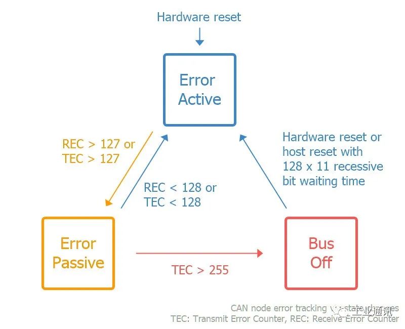
The purpose of CAN error tracking is to limit errors by reducing the privileges of problematic CAN nodes. Specifically, let's look at three possible states:
Activity Error: This is the default state of each CAN node, in which it is able to transmit data and trigger an “active error flag” when an error is detected.”
Passive error:In this state, the CAN node is still able to transmit data, but now triggers a “Passive Error Flag” when an error is detected. In addition, the CAN node must now wait for an additional 8 bits (also known as a pause time) in addition to the 3-bit interrupt time to resume data transmission (to allow other CAN nodes to take control of the bus).
The bus is closed:In this state, the CAN node disconnects itself from the CAN bus and can no longer transmit data or trigger an error flag.
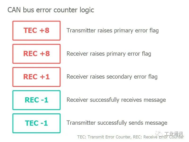
Each CAN controller keeps track of its own state and acts accordingly, and the CAN node transitions state based on the value of its error counter. Specifically, each CAN node keeps track of the Transmit Error Counter (TEC) and Receive Error Counter (REC):
- If REC or TEC exceeds 127, the CAN node enters a passive error state.
- If the TEC exceeds 255, the CAN node goes into bus shutdown.
So how does the error counter change? Before we get into the logic of how to increase/decrease the error counter, let's revisit the CAN error frames and major/minor error flags.
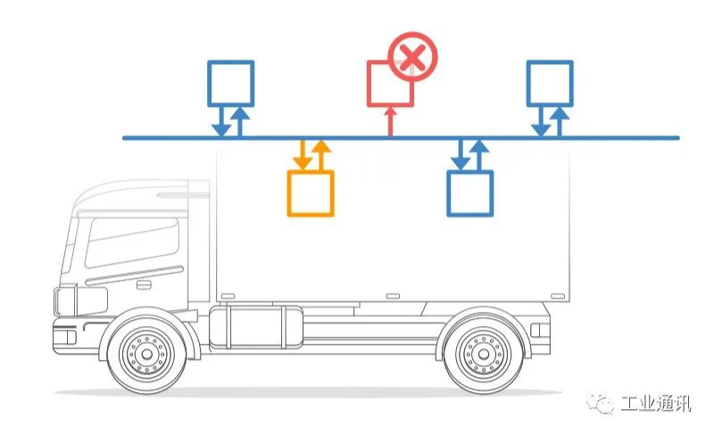
As is evident from the CAN error frame icon, a CAN node that observes a significant bit after its own sequence of 6 significant bits will know that it has triggered a major error flag. In this case, we can refer to this CAN node as the “finder” of the error.
At first, it may sound positive to have a CAN node repeatedly discover errors and react quickly by flagging errors before other nodes. However, in practice, the discoverer is often the culprit of the error.
CAN/LIN Data and Error Logger
The Avision CANedge1 allows you to easily log data from a 2xCAN/LIN bus to an 8-32GB SD card and supports logging of CAN/LIN errors. Simply connect it to your car or truck to start logging and decode the data via free software/API. In addition, the upgraded CANedge2 adds WiFi functionality, allowing you to automatically transfer data to your own server and update the device wirelessly.
In addition, we also provide our customers with hardware devices such as CAN cards, data acquisition modules, CAN gateways and converters, and the Kvaser CANLIB SDK. Waiting for software.For more information about CAN technology services and CAN products, please feel free to contact us!