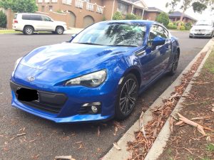
Failure phenomenon
A 2022 AITOM5 add-on hybrid with a 1.5T engine and generator as a range extender with approximately 36,000km. the vehicle was repaired due to a rear-end collision, and was slow-charged after the repairs.The charging port cover indicator does not light up.(Figure 1),However, the instrument indicates that the vehicle is charging and the vehicle is charging normally。

Fig. 1 Charging hole cover indicator does not light up during slow charging.
Fault Diagnostics
由Figure 2It can be seen thatThe charging hole cover indicator is controlled by the Body Controller (BCM) via the LIN bus.. By.Figure 3It can be seen thatBCM, Charge Hole Cover Indicator, Kick Sensor, Battery Sensor and Data Diagnostic Interface on LIN3 BusThe main control unit is BCM.

Fig. 2 Charging port cover indicator control circuit

Fig. 3 LIN3 Bus Schematic
With a fault detector.No fault code storage in BCMRemove the left side trim panel of the luggage compartment. Remove the interior panel on the left side of the luggage compartment, according to theFigure 2Measure the voltage between terminals 1 and 2 of the charging hole cover indicator lamp lead connector to 14.02 V; test with a 10 W light bulb.The light bulb can be lit normally, which means that the power supply and the iron of the charging hole cover indicator are normal.Measure the voltage between the charging hole cover indicator lamp lead connector terminal 3 and terminal 2, 10.26 V, normal.
From the measurements, theThe wiring of the charging hole cover indicator is not abnormal, and it is suspected that the charging hole cover indicator was damaged before the collision.The charger cover indicator was replaced and the car was tested. Test drive the car after replacing the charging hole cover indicator.Faults remain. Use an Acer pico oscilloscope to measure the LIN signal waveform at the charging hole cover indicator light lead connector terminal 3 (Figure 4),Signal transmission, high level about 13 V, low level about 1 V, normal。

Fig. 4 LIN Signal Waveform
Serial decoding of LIN signals (Figure 5),Found that there are 4 red IDs (61, A6, E7, F0) in the data area that are not transmitting data.。

Fig. 5 Serial decoding of LIN signals
ID E7 in the election (Figure 6The LIN signal is only the question header sent by the master unit BCM, and there is no answer from the unit.At this point in the diagnosis, it is suspected that the fault is caused by the loss of some data on the LIN bus.。

Fig. 6 IDs of selected data areas E7
Further Diagnosis
First of all, the software and hardware of the BCM were re-calibrated, and the fault remained the same. Compare the software version of the BCM with the same model of vehicle and it is the same.
After asking the sheetmetal repairman about the rear end of the car, I was told that the rear end was not severely impacted and the rear bumper harness and kick sensor were replaced. Since the kick sensor is on the same LIN bus as the charging hole cover indicator, the rear bumper harness and kick sensor were replaced.Suspected faulty replacement kick sensors.. Remove the rear bumper.Take off the kick sensor cable connector, and found that the charging hole cover indicator light can be lit up.Compare the new and old kick sensors. Comparing the new and old kick sensors, the appearance is exactly the same, but there is a difference in the part number, the part number of the old one is 3778081-RK01, and the part number of the new one is 3778081-SY01, which confirms that the replacement kick sensor is the wrong model.
fault resolution
Replace the correct model of kick sensor and try the car, the charging hole cover indicator can light up normally, trouble solved.。
Fault Summary
Measure the LIN signal waveform again and perform serial decoding (Figure 7),Only ID F0 in the data area is not transferring data.。

Fig. 7 Result of serial decoding of LIN signal waveform of normal vehicle
Remove only the charging hole cover indicator light lead connector.Extra ID in data area E7 is not transmitting data.(Figure 8)。

Fig. 8 Results of LIN signal waveform serial decoding after disconnecting the charging hole cover indicator cable connector
Disconnect the kick sensor cable connector only.Extra ID in data area A6 is not transferring data.(Figure 9)。

Fig. 9 Serial decoding result of LIN signal waveform after disconnecting the kick sensor lead connector.
Disconnecting only the battery meter lead connector.No data transfer for ID B4, ID F5 and ID 76 in the data area.(Figure 10)。

Fig. 10 Results of serial decoding of LIN signal waveform after disconnecting the wire connector of the current meter.
Analysis suggests that the replacement kick sensor is of the wrong model, resulting in the kick sensor and charging hole cover indicator not being able to communicate with the BCM, but there is no corresponding fault code stored in the BCM, which makes diagnosis difficult.。