Introduction
Modular instruments reduce the size of traditional instruments so they can be mounted on circuit cards. Multiple cards can be inserted into a frame with common computer interfaces, power supplies and interconnections. Modular instrument frames include computers with standard PCIe interfaces, PXI test frames, or LXI-based boxes. Typically, engineersUse multiple cards and configure them into a test system. The system may contain multiple instruments, a single instrument type with multiple channels, or a combination of both.。
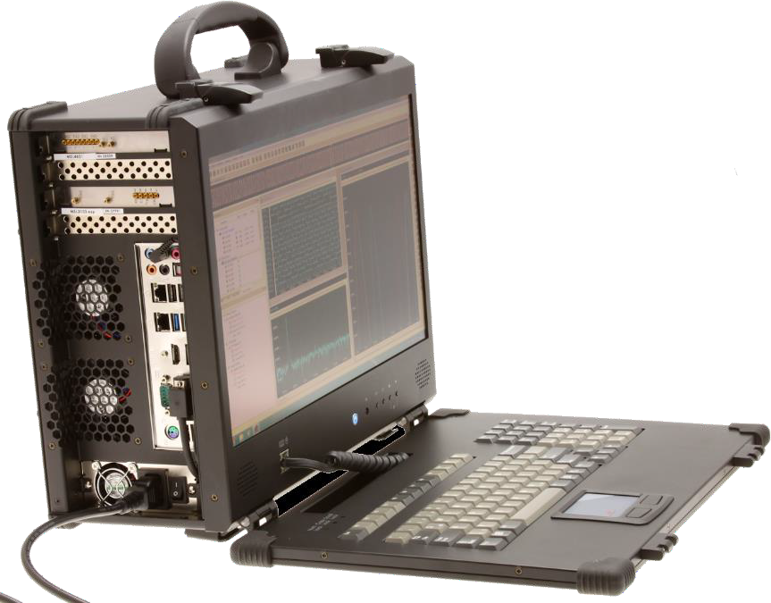
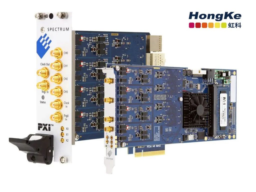
The picture on the right shows a portable computer with two PCIe modular digitizers. This compact, self-contained unit can be used inside the vehicle and allows measurements to be taken while the vehicle is in motion.
PXI-based modular systems are less autonomous, but offer more modular instruments in a single crate. They require an external display and keyboard. LXI-based systems such as Spectrum's digitizerNETBOX are very easy to use.Ideal for lab installations and mobile use, it provides a large number of channels and connections via LAN for direct connection to laptops or remote control room monitoring.。
In-vehicle Electronics
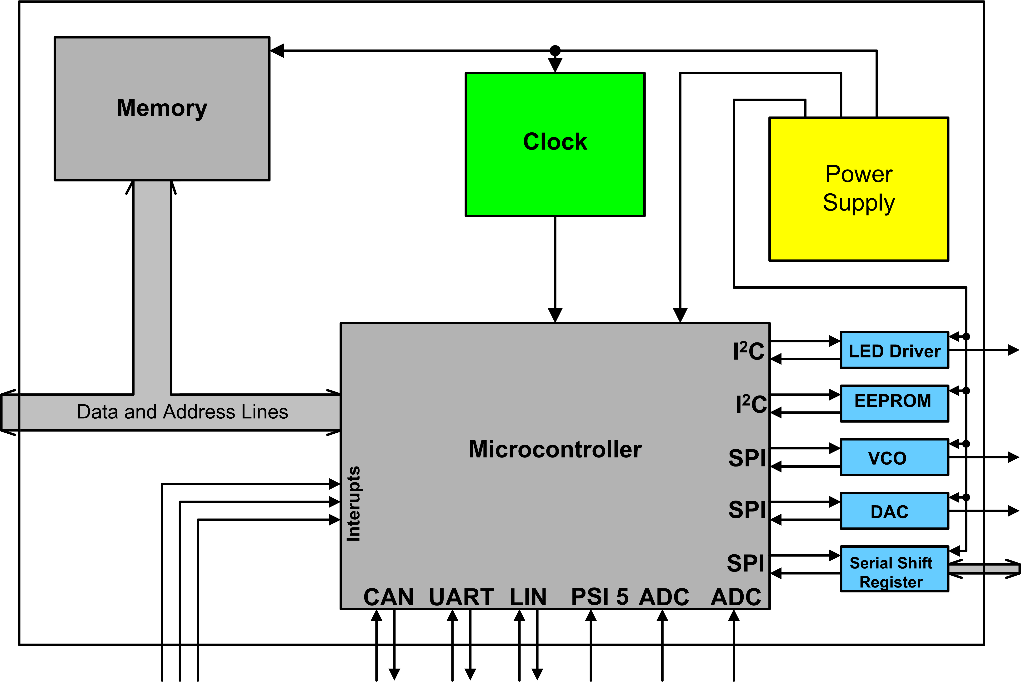
The foundation of an in-vehicle electronics subsystem is the microprocessor. The figure on the left shows a generic in-vehicle microprocessor with microcontroller, memory, and peripheral interfaces. Sensors and other controllers communicate using various vehicle-specific interfaces shown on the bottom of the microcontroller.
These microprocessors differ from standard microprocessors in having higher environmental and reliability standards, as well as the addition of specialized vehicle buses and interfaces such as CAN, LIN and PSI5. These interfaces allow the microprocessor to communicate with other processors, sensors, and actuators.
The Controller Area Network or CANbus is the most complex data bus shown here and is the backbone of many automotive data links. In its basic form, it uses differential signals with 8-bit packets to exchange data over a two-wire bus at speeds ranging from 20kb/s to 1Mb/s. The CAN Flexible Data Rate (CAN FD) is a newer version of CAN that allows for the exchange of data at the same rate as the CAN bus. A newer version, CAN Flexible Data Rate (CAN FD), extends the data content to 64-bit packets, which are exchanged at speeds of up to 12Mb/S. The CAN FD is a newer version of CAN Flexible Data Rate (CAN FD), which is a newer version of CAN Flexible Data Rate (CAN FD).
The Local Interconnection Network or LIN bus is a lower cost bus that helps toReduce costs for non-critical applicationsIt uses two, four or eight bytes of data to run at up to 20kb/s over a single cable. It uses two, four or eight bytes of data frames running at up to 20kb/s over a single wire.
The PSI5 interface is used to connect multiple sensors to the electronic control unit and has been used as the main sensor communication bus for airbags and related restraint systems. It is a two-wire bus running at speeds up to 189kb/S using Manchester encoding.
Application of Digitizer
The most commonly used modular instrument is the digitizer. A digitizer is an electronic acquisition device that acquires analog waveforms, samples and digitizes them through an analog-to-digital converter (ADC), and sends the digitized samples to a buffer where they are stored before being processed by a computer. Modular instrument suppliers such as Spectrum offer digitizers with 8- to 16-bit ADC resolution, analog bandwidths up to 1.5 GHz, and sampling rates up to 5 Giga samples per second (GS/s), with 1 to 16 channels per card. In preparation for synchronizing multiple cards, each system allows up to 16 cards (or up to 256 fully synchronized channels). These instrument systems can be reconfigured indefinitely to acquire, store and measure signals in an in-vehicle embedded system.
Spectrum digitizers can be selected to match the data rate and bandwidth requirements of each interface, as well as the more common processors and associated operations.
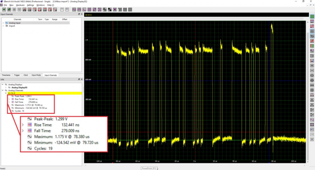
Consider the task of monitoring the CANbus interface. The digitizer used for this measurement has remotely configurable inputs that allow single-ended or differential inputs for each channel. In this case, the differential input was used. The results are shown in Figure 3. The acquisition is shown using Spectrum's SBench6 software, which allows the physical layer of the interface to be analyzed. The amplitude and timing of the signals can be verified to ensure compliance with the CANbus standard.
Basic measurements of signal amplitude, including peak-to-peak, maximum and minimum values, characterize the data package. Additional timing measurements of rise and fall times ensure the integrity of the bus signal.
In addition to the physical layer, Spectrum digitizers can interface with third equations such as LabVIEW and MATLAB where waveform data can be decoded and the protocol layer explored. Experienced programmers can create custom programs in C, C+, Python or similar languages using Windows and Linux drivers to develop custom decoding operations.
Signal Source Simulation
In many engineering projects, testing may be put on hold because key components are missing or it is too expensive to perform physical tests. Arbitrary function generators (AWGs) can be used to create almost any waveform and analogize missing components. Arbitrary waveform generators are digital signal sources that operate much like an inverse digitizer. In the case where the digitizer samples the analog waveform, digitizes it, and then stores it in its acquisition memory, the AWG has a digital description of the waveform stored in the waveform memory. The selected waveform samples are sent to a digital-to-analog converter (DAC) and then output as analog waveforms through appropriate filtering and signal conditioning.
For simulation, you can use AWG as an alternative if you have access to the missing portion of the response waveform acquired by the digitizer, or if it can be created by analysis. A common problem is the ability to output a series of waveforms, each representing a different state of the system under test. While this can be accomplished with multiple generators and some sort of switching, there is a more efficient method.
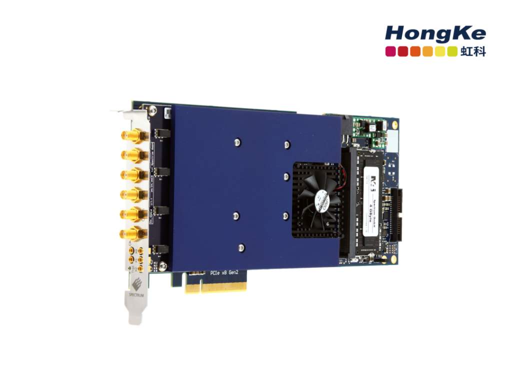
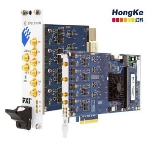
AWGs with full-featured sequence modes, such asSpectrum M4i.66xx-x8 series (pictured above), capable of switching between waveforms in real time, even without the need to reload different waveforms in time AWG's waveform memory is segmented. The AWG's waveform memory is segmented to store each waveform required for testing, each in its own segment. The AWG traverses the waveforms step-by-step under computer control according to the instructions stored in the separate sequence memory. The contents of the sequence memory can be updated or changed without affecting the output state of the AWG. This sequence mode operation allows the test sequence to be changed adaptively based on test results. This capability greatly reduces test time and increases test thoroughness.
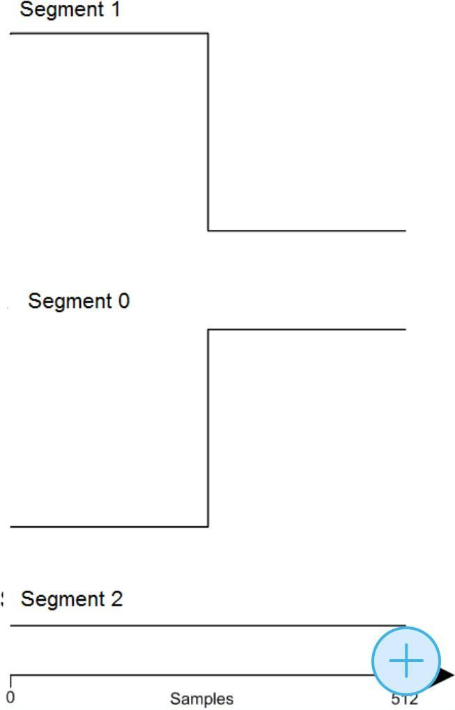
For example.The AWG can be used in place of the PSI5 sensor to generate a series of programmable output codes. PSI5 uses Manchester encoding. Manchester code always places a transition in the middle of each bit cycle. It may also (depending on the information to be transmitted) have a transition at the beginning of the cycle. The direction of the intermediate bit transition indicates the data. Transitions at cycle boundaries carry no information. They exist only to put the signal in the correct state to allow intermediate bit transitions. Guaranteed transitions allow the signal to self-timer. To generate a PSI5 packet, three waveform segments are required, as shown in Figure 2. Logic “1” (Segment 1) indicates conversion from high to low. Logic “0” (segment 0) indicates a low-to-high conversion.
By using these components to define three waveform segments, any combination of data patterns can be synthesized. This means that the contents of the packet can be changed by rearranging the order of the three segments. Figure 3 shows four examples of PSI5 packets, each consisting of three segments but each with different data content.
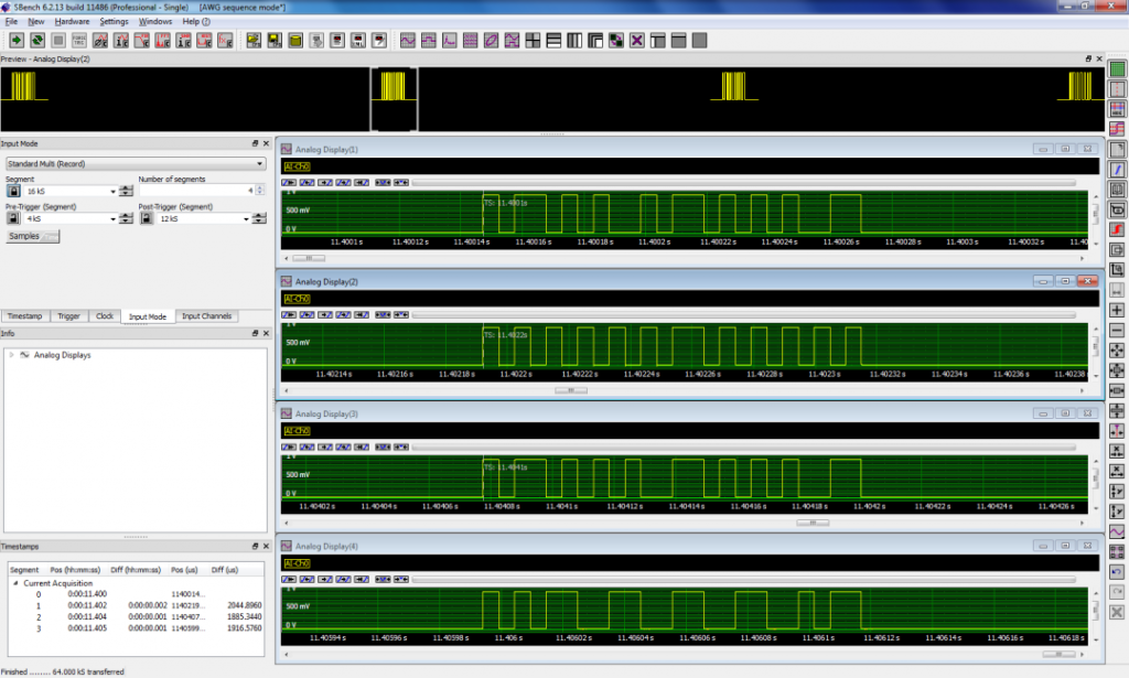
In this example, the segments are set to a length of 512 samples, and the clock rate is 50 MS/s, so the duration (TBIT) of each element will be 10.24 μs. The data packets are separated by baseline signals that last for more than two bit clock cycles. The AWG is controlled using a MATLAB script that assembles four different data patterns from three segments for this test. Switching between data packets is done seamlessly without interruption.
Power Sorting
Another area of concern is the proper sequencing of the power rails during power-up or power-down. Embedded computing systems often require multiple supply voltages to power microprocessors, memory, and other on-board devices. Most microcontrollers have a defined sequence in which voltages must be applied to prevent problems such as lockup. Power management ICs (PMCs) or power sequencers perform many sequencing tasks. Since most processors use multiple voltages, a digitizer with up to eight inputs is ideal for such measurements. In addition, large acquisition memories are required because the power-up/power-down sequences take milliseconds.
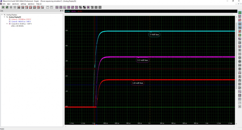
Figure 4 shows an example of a simple power sequence measurement. Three power rails (5, 3.3 and 1.8 volts) are monitored. The expectation is that the voltage levels should rise monotonically in the desired sequence. In this example, the 5-volt supply is turned on before the other supplies, followed by the 3.3-volt and 1.8-volt lines.
The time delay can be measured using a cursor, as shown in the figure, where the time delay between the 5-volt and 3.3-volt buses is measured to be 35.5 μs.
This type of power measurement can be extended to measure ripple, modulation and transient response.
Mechanical Measurement
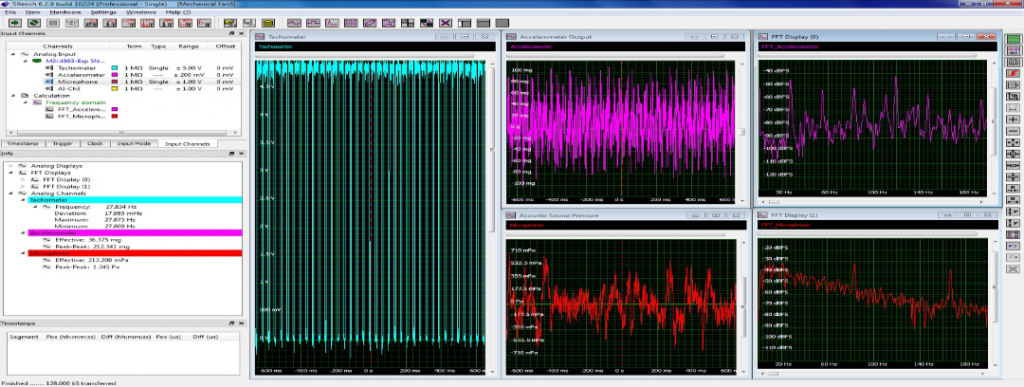
Modular instruments can also be used for mechanical measurements with suitable sensors. Figure 5 shows a series of mechanical measurements performed on the fan.
This SBench6 screen image shows the tachometer output in the leftmost grid. The waveform consists of one pulse per revolution of the fan. The fan speed is read by measuring the frequency of this signal. The frequency reading in the information pane in the left center of the graph reads this frequency as 27.8 Hz (revolutions per second). Multiply this frequency reading by 60 to get a fan speed of 1668 revolutions per minute (RPM). Statistical readings showing the minimum, maximum, and deviation of the frequency are displayed below the frequency reading.
The accelerometer output is displayed in the upper center pane labeled "Accelerometer Output". A custom vertical scale has been set using the analog channel settings to read g's directly. The signal peak-to-peak and effective (rmS) amplitude measurements are displayed in the information pane. The time-domain view of the signal is a little difficult to interpret, so the Fast Fourier Transform (FFT) of the signal is calculated and displayed in the upper right display pane.
The FFT shows the frequency components that make up the acceleration signal. The frequency domain or spectral view of the FFT provides an easier physical interpretation because it separates the various frequency components. The leftmost peak appears at 27.8 Hz, the rotational frequency of the fan motor. The other spectral components correspond to the physical properties of the fan.
The microphone output is shown in the bottom center grid, scaled to the sound pressure. The data has also been rescaled to read in pressure units, i.e., pascals. The measurement in the information pane shows the peak-to-peak value and effective amplitude of the signal. As in the case of vibration signals, the acoustic FFT provides a great deal of physical insight.
Conclusion
Ideally suited to vehicle test and measurement applications, the digitizers offer a large number of channels with resolutions from 8 to 16 bits. Digitization rates up to 5 GS/s allow selection of fast or slow sampling to match the application. Arbitrary waveform generators support simulated scenes. They allow testing even when components are missing. A choice of PCle, PXI or LXI configurations meets the needs of portable or laboratory testing.