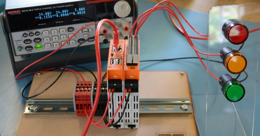
Traffic signals are a regular feature in industrial or construction sites. In this article, we take RevPi Core3 as an example, and use an industrial-grade Raspberry Pi as a soft PLC, programmed with Logi.CAD 3, to create a stable and reliable application facility.
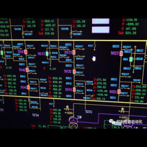
PLCs are specifically designed to control manufacturing processes and can be programmed more easily using a standard set of instructions. They were originally developed in the automotive manufacturing industry to replace a complex, hard-wired collection of relays, timers, and sequencers that previously controlled manufacturing processes and were difficult to update.
Today, the RevPi Industrial Raspberry Pi is a modular system with protected inputs and outputs in a ruggedized industrial package that leverages the Raspberry Pi's extensive ecosystem and software support, combined with a programmable PLC that complies with the IEC 61131 industry standard for DIN-rail mounting.
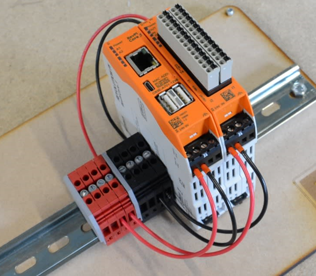
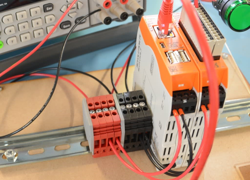
[Modules and tools used in this article
- RevPi core 3 module
- DIO Module
- Some terminals on DIN rail
- Three 24V LEDs
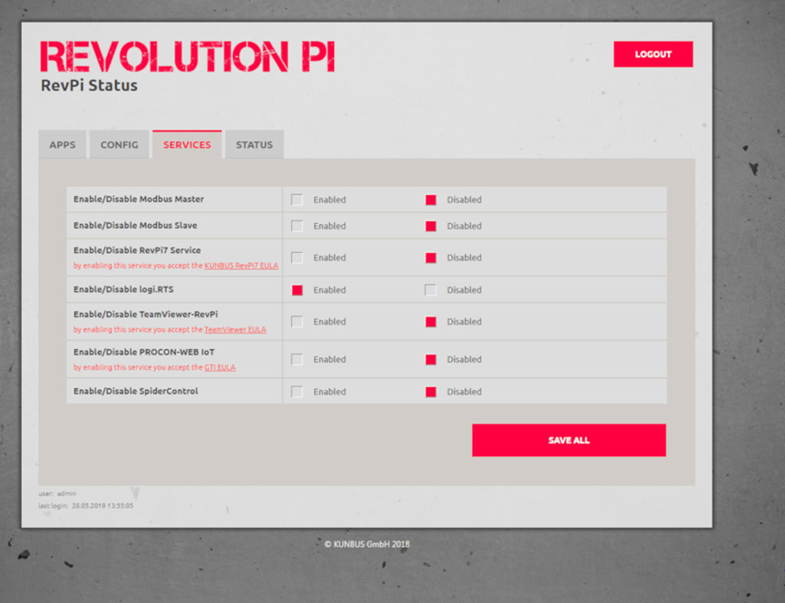
Use the first output connection on the RevPi DIO module with a power supply of 24 V. Initial RevPi and DIO module configuration is accomplished through the Pictory Configuration Tool running in a web browser.
【 Support Resources 】
Like most PLCs, the Revolution Pi is programmed on a PC and then downloaded to the module over the network. Programs can be downloaded to the module via the network by going toKunbus Quick Start GuideCAD 3 to see how to create a control application for Revolution Pi using logi.CAD 3 and get a link to download the software.
Also available at logi.cals (developers of logi.CAD 3).TeachingPlusKUNBUS Official Instructional MovieThe instructions are quick to follow.
【 Installing and using Logi.CAD 3 】
First, enable the PLC programming environment by returning to the Revolution Pi setup page in your web browser, selecting the Services tab and enabling Logi.RTS.
Install Logi.CAD 3 when done (can utilize tools other than Window's native decompressor, such as 7Zip, as it cannot handle the length of some file names)
Next, start the program by double-clicking on the logiCAD3.exe file, and at this stage, follow the tutorial videos for smooth operation.
To search for RevPi sample projects in the logi.CAD tutorial, open the File menu, go to New/Project... and open “Logi, CAD 3 Template”.
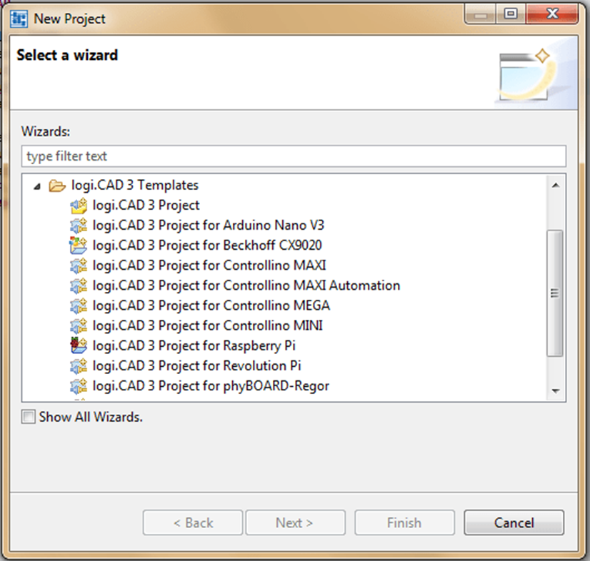
Find “logi.CAD 3 Project for Revolution P”, open it and name it “Example” when prompted for a “Project Name”. "and save it in the default location.
Once opened, follow the instructions in the guide to enter the IP address of the RevPi in the globals/sample file.
Then go back to Pictory, check the configuration set and change the names of the 3 outputs that will be used, then save the configuration by going to File/Save and activate it by clicking Reset Driver in the Tools menu.
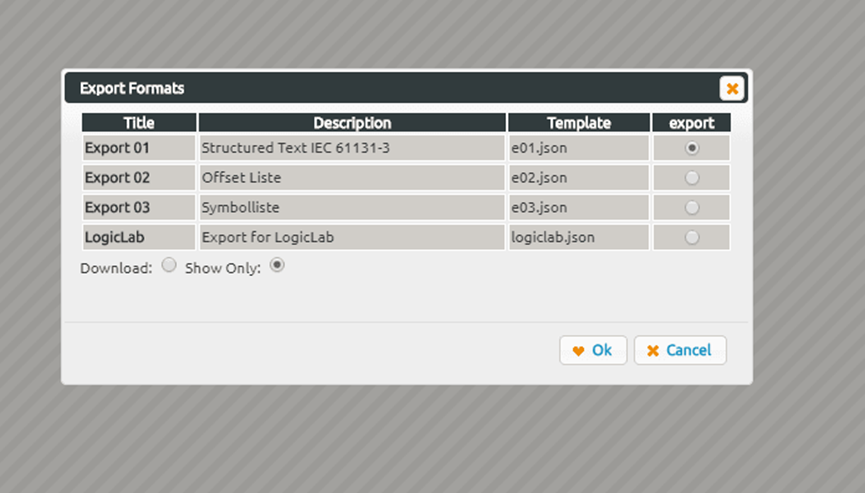
Then export the configuration details for use in logi.CAD 3. This is done in File/Export by selecting the structured text IEC 61131-3 in the popup box and selecting “Display only”, which will create the global variables and open them in a window.
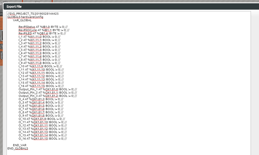
Copy the contents of the window and return to logi.CAD3, open the sample.global file in the globals folder, delete its contents and paste the text from the clipboard.
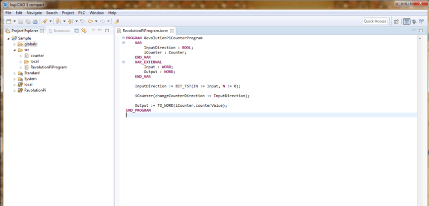
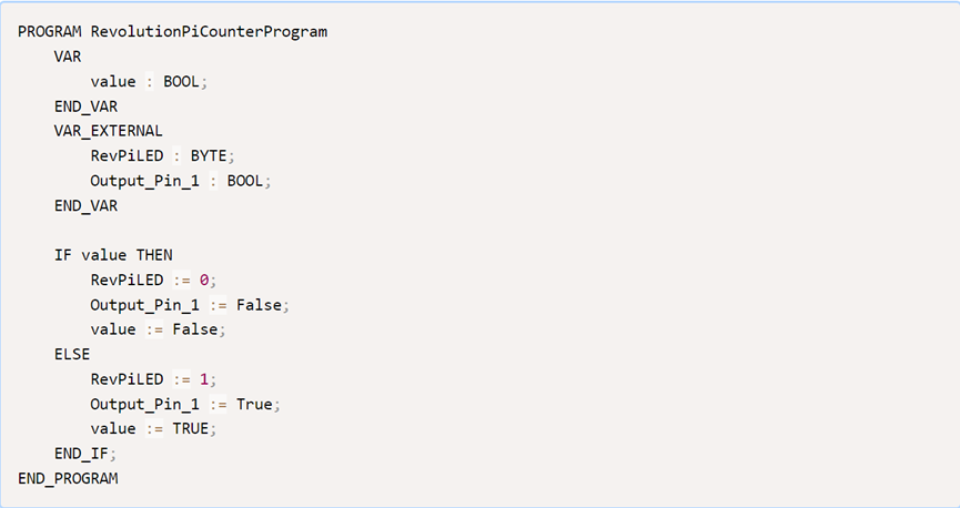
Then replace the code in the RevolutionPiProgram.iesct file with the code in the guide:
Switch to the example view by clicking on the tab at the top of the left side column and selecting RevolutionPi/RevolutionPiResource. click on the green gear icon to connect to the Revolution Pi and then click on the “Build and Upload” button. Then you will see the LED on the RevPi Core3 and the LED connected to Revolution Pi DIO pin 1 blinking.
Trivia
In the next article, a step-by-step description of the sequential switching of the signals will be given, which will cover the basics of the PLC programming language/environment.