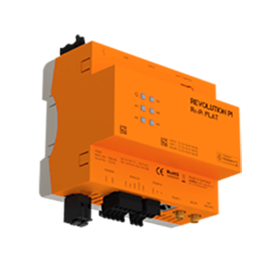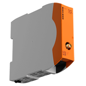
RevPi DIO module
RevPi DIO modules, expand your Revolution Pi system by adding digital I/O expansion modules.
Download
Description
I. Overview
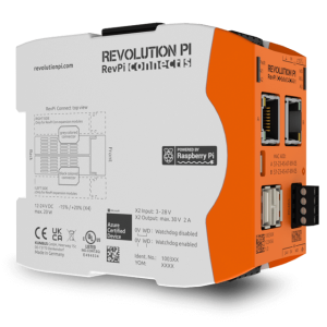
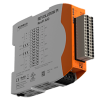
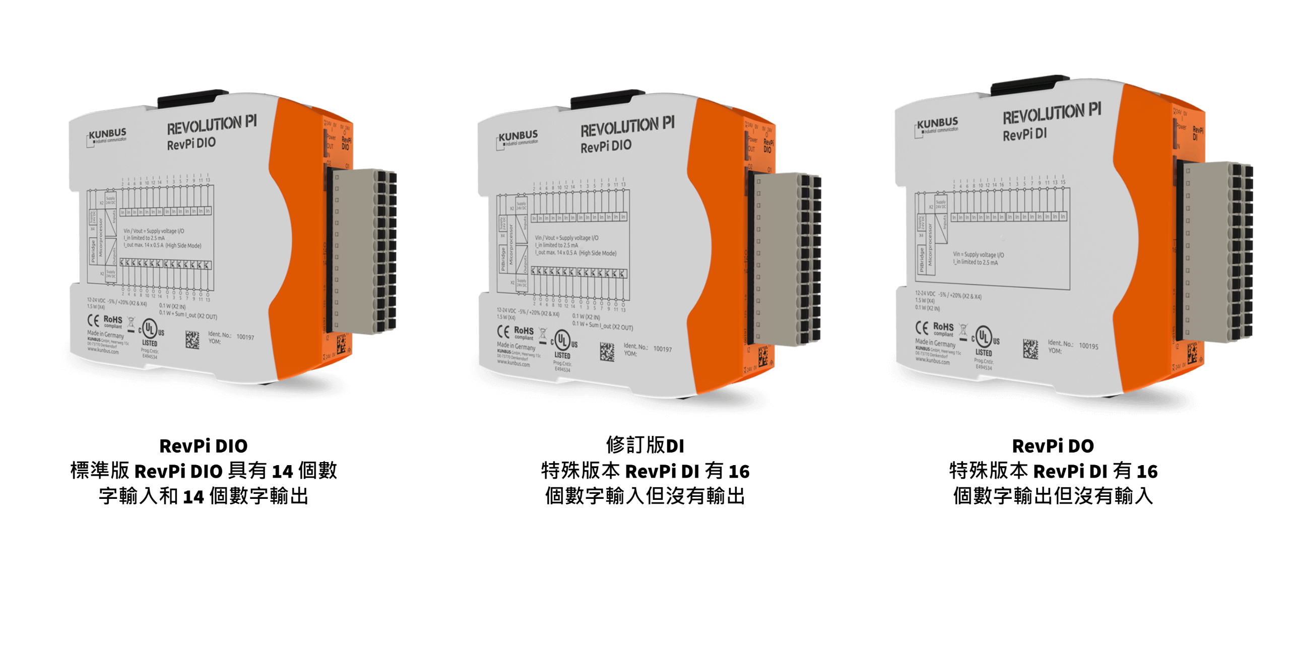
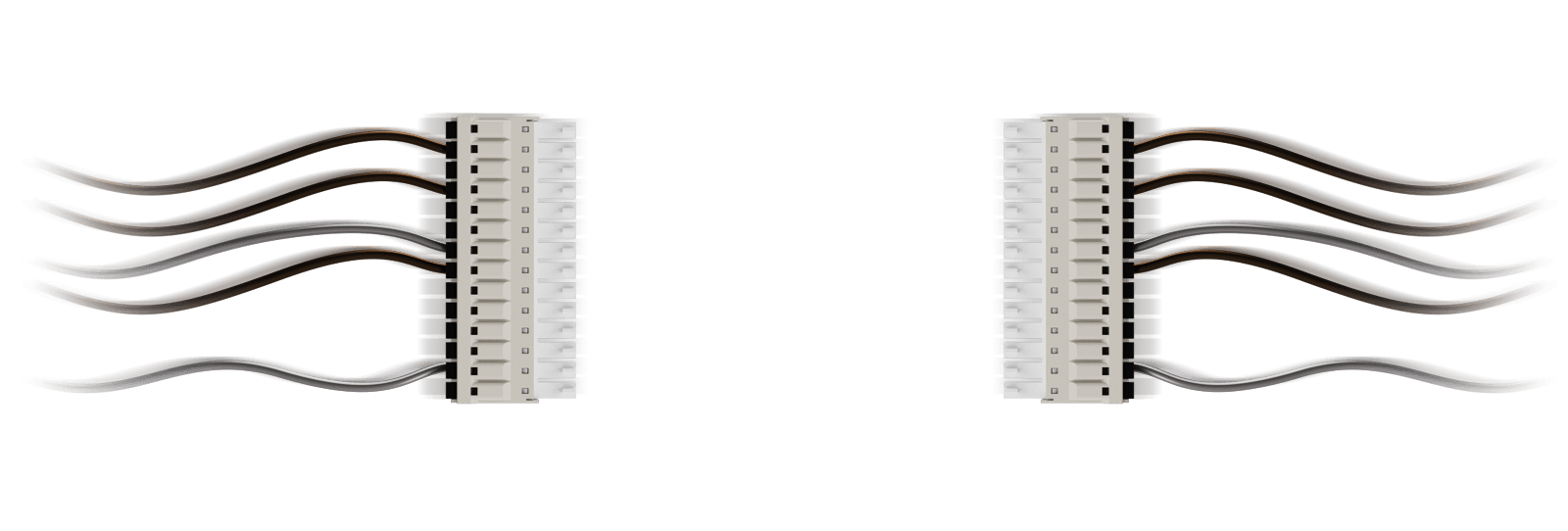
To turn the Revolution Pi into an industrial control unit, a variety of digital I/O modules can be connected to the base module, the RevPi Core.The I/O modules are available in three versions. All front-ends have the same 28-pin I/O connectors (the connectors have two rows of 14 pins each - two suitable 14-pin socket connectors with spring-loaded clamping points are provided for connecting twisted wires up to 1.5 mm²). In addition to the standard version with 14 digital inputs and 14 digital outputs, there are two special versions with 16 digital inputs or 16 digital outputs.
All versions have current isolation between the PiBridge logic circuit and the inputs. The RevPi DIO version has additional current isolation between input and output. All versions are protected against interference according to EN 61131-2 and can be operated at relative temperatures up to 93 % between ambient temperatures of -40 °C and 55 °C. Humidity. In addition, all digital I/O modules are UL listed (UL-File-No. E494534).
II. Module Types
III. Digital Input
The DC input has a voltage threshold which complies with EN 61131-2 type 1 and type 3 input definitions for a 24 V supply voltage. The input current is clamped at a maximum of 2.4 mA. This specification does not address the 12 V input definition, so we cannot test any compliance. However, the threshold is reasonably low with the supply voltage. If the supply voltage falls below 9 V, an alarm is sent to the RevPi Core/Connect. This can be used as an indication of unreliable input values that no longer comply with the 24 V digital input specification.
There is an adjustable low-pass filter to prevent the input signal from jumping. This filter can only be applied to all or none of the inputs. The filter only propagates input values that are stabilized for at least 25 µs, 750 µs or 3 ms (values are part of the configuration). All inputs are protected against ESD, bursts and surges according to EN 61131-2.
Digital Output
Each output can be individually configured as a high-end switch up to 500 mA current load or a push-pull output up to 100 mA. Independent of its output mode, each single channel is protected against overcurrent and short-circuit. A hardware watchdog circuit monitors the SPI data exchange between the MPU and the output circuits. If there is no SPI traffic, the output is forced to 0 (safe state). The outputs are also forced to a safe state if the output power drops or the output circuitry reaches an overheated state. These types of error conditions, as well as the short-circuit status of each channel, are cyclically transmitted to the RevPi Core.
Each output can also be configured to detect open-circuit load conditions in high side switching mode and send an alarm to the RevPi Core. Like the inputs, all outputs are protected against ESD, burst and inrush according to EN 61131-2.
V. Module functions
The switching status of inputs and outputs is exchanged cyclically via PiBridge with the central processing image of the RevPi Core using the PiControl driver. In addition to the switching status, possible error conditions (diagnostic data) and configuration data are also circulated.
During startup, module detection identifies all modules and their physical location to the left or right of the RevPi Core. After this detection phase, the modules obtain their acyclic configuration data. The system then enters the process data transfer phase where data is exchanged using the PiBridge's RS485 channel and time-optimized protocols.
The I/O module RevPi DIO is also equipped with PWM (Pulse Width Modulation) and counter inputs. The PWM function can be activated individually for each of the 14 outputs. This means that instead of transmitting only 1 bit per channel, a full byte value containing the pulse width from 0 to 100 (percentage value) is transmitted. Although our output driver ICs are capable of handling high frequency PWM, the RevPi DIO is limited to low frequency only, as PWM is implemented using software switching. One of the following PWM frequencies can be selected by configuration (find the corresponding resolution in parentheses for the smallest percentage step): 40 Hz (1 %), 80 Hz (2 %), 160 Hz (4 %), 200 Hz (5 %) and 400 Hz (10 %).
The counter function can be activated for each of the 14 input channels. This results in 32-bit values for each counter being accessible in the central process image.