Automotive Diagnostic Communications Overview
Automotive diagnostic communications is a complex and critical area that relies on the layered architecture of the Open Systems Interconnection (OSI) model and a set of carefully designed standards and protocols. By understanding the application of these standards and protocols across the layers of the OSI model, we can better ensure the efficient operation and continued innovation of the automotive electronics architecture. This article will help you understand the use of the OSI model layers and the associated automotive SAE standards for diagnostic testing.

Photo 1: Close-up of engine and vehicle parts
Diagnostic Protocols and the OSI Model
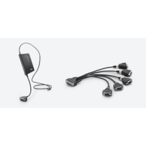
Fig. 2 shows a conventional communication system used for diagnostic applications.Vehicle Communication Interface (VCI)Connects a diagnostic tester (TST, also known as a scan tool) to the vehicle's diagnostic link connector (DLC). For diagnostic purposes, the TST sends diagnostic service requests to the vehicle and receives diagnostic service responses from the vehicle.

Figure 2: Conventional Communication System with Vehicle Communication Interface
The Diagnostic Communication Protocol provides for requests and responses. The International Standardized Diagnostic Communication Protocol is based on the International Standardized Diagnostic Communication Protocol.Open System Interconnection (OSI) Basic Reference ModelThe model divides the communication system into seven layers (Fig. 3).
 model")
Figure 3: The 7 layers of the Open System Interconnection (OSI) model
Diagnostic communication requests and responses are modeled in the open system interconnectionApplication Layer (L7)specified on the L7. Examples of L7 protocols include UDS on CAN and OBD on UDS, where UDS is an acronym for Unified Diagnostic Service and OBD is an acronym for On-Board Diagnostic System.Unified diagnostic services are defined in ISO 14229-3.In SAE J1979-2, an in-vehicle diagnostic system based on the Unified Diagnostic Service is specified (Fig. 4).

Fig. 4: Diagnostic communication mapped according to OSI model
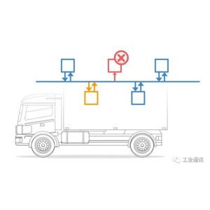
OBD System Transformation in the ZEV Era
As the automotive industry raises its environmental requirements, especially for the rise of Zero Emission Vehicles (ZEVs), On-Board Diagnostic (OBD) systems and their related standards are evolving.
The original On-Board Diagnostic (OBD) system, based on the SAE J1979 standard, is primarily used to monitor and reduce the emission of hazardous pollutants from conventional internal combustion vehicles.These include carbon monoxide (CO), nitrogen oxides (NOx), hydrocarbons (HC) and particulate matter (PM). The application layer protocol SAE J1979 and its “Onboard Diagnostic Mode” on CAN have been protecting our environment from harmful pollutants for decades.

Figure 5: ISO 14229 specifies 26 generic diagnostic services.
With the adoption of Unified Diagnostic Services (UDS) by regulators, the SAE J1979 standard has been refined into a number of components, of whichSAE J1979-2 is specifically designed for internal combustion vehicles.but (not)SAE J1979-3 for zero-emission vehicle propulsion systemFor zero-emission vehicles, emission-related fault monitoring is replaced with propulsion system-related fault monitoring. For zero-emission vehicles, emission-related fault monitoring is replaced with propulsion system-related fault monitoring.

Figure 6: SAE J1979-3
More than just a specific OBD specification, SAE J1979-3 is associated with regulations that require the standardization of diagnostic data and powertrain algorithmic data to support ZEV maintainability, warranty compliance, facilitate the ZEV used vehicle market, and provide the data needed to confirm that a vehicle meets battery durability requirements. It is also expected that future releases of SAE J1979-3 may include additional ISO 14229 services, subfunctions, DIDs, and ZEV-related DTCs.
Update on SAE J1979-3 and SAE J1979-2
SAE J1979-2 and -3 are both variants of ISO 14229 (Unified Diagnostic Service), but are limited to emissions-related failures and zero-emission vehicle advancement-related failures, respectively, and associated diagnostic information.
California Air Resources Board (CARB)Requires a new diagnostic communication protocol:
- SAE J1979-2: Starting in 2023, all vehicles with internal combustion engines must support SAE J1979-2 by 2027.
- SAE J1979-3: By 2027, all Zero Emission Vehicles (ZEVs) and Plug-in Hybrid Electric Vehicles (PHEVs) must support SAE J1979-3.

Figure 7: Traditional Agreements and Modern Extensions
Neither J1979-2 nor J1979-3 support vehicle manufacturer-specific diagnostic applications such as calibration or brushing programs. For performance reasons, theISO 14229-5 Standardized Unified Diagnostic Service for Internet Protocol (UDSonIP)It has become the latest technology for writing programs.