By Ben Martins
You might think that the smaller the engine, the easier it is to work on a construction machine. This is far from the truth! The smaller the engine, the harder it is to build. This little Komatsu 14T is no exception.
I was asked to look at this 2016 Komatsu 138US where the customer was complaining that the engine was shuddering and emitting black smoke from the exhaust when the machine was activated with an oil pressure load. As with all diagnostics, a customer visit is important to ensure that the fault can be reproduced as well as any other relevant information such as whether it has been recently refueled.
When we spoke to the operator, we learned that the machine was worse when it was warmed up, that there were no warnings displayed on the gauges, and that the failure had occurred without any warning. Fortunately, the machine had not yet been started, allowing us to observe its warm-up phase to verify that the problem would be worse once it warmed up. Normally, when the problem we were facing is temperature related, we can't test at any temperature!
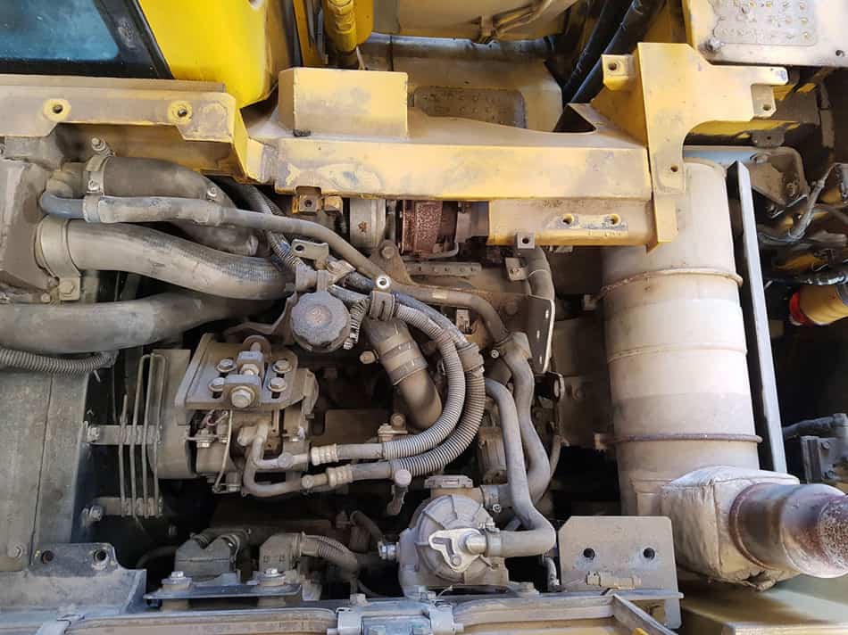
We did a quick check around the engine bay to make sure there were no obvious faults. But as mentioned earlier, the smaller machine crams everything into a very small space, and when you can't even see the jet pumps and pipes, you just know you're going to come home with red, sore arms!
There were no obvious problems when starting the machine, and no unusual noise or smoke. Therefore, we omitted the relative compression test. By keeping the machine running while warming up, we were able to understand customer complaints. By keeping the lever in this position with the arm all the way up, we can make sure that the hydraulic oil pump is applying its maximum torque to the engine, which we are loading at the moment. When the engine has not yet warmed up, the fault is not yet apparent. We have noticed a slight decrease in engine speed, but we are not aware of the customer's complaints of engine shuddering and black smoke. After warming up the machine to a certain temperature, we observed some crosstalk data on the cab display.
Komatsu's machines have a wealth of resources built into them that allow technicians to view some of the serial data without the need for scanning tools. By accessing the service catalog, we can now view data such as target and actual EGR locations, MAF, target and actual rail pressure and hydraulic fluid pressure, which means we can begin to develop a plan of action.
Glad that the hydraulic system part looked normal, we moved the hydraulic system to the top of our action list. As the engine continued to warm up, the problem began to become apparent. While keeping the hydraulic system loaded, the engine began to shudder, and the rpm's dropped, emitting black smoke. The black smoke is caused by poor combustion and can be categorized as air, fuel, and compression being the biggest factors and the top three items on our action list.
For compression, since the machine started smoothly and did not misfire even in a faulty condition, we moved it to the list and focused on air and fuel. For construction machines, the most common problems are usually fuel related, so getting rail pressure is important. I try to capture engine speed at all times, as it's diagnostically helpful to be able to plot the crankshaft acceleration and deceleration curves over the course of four cycles. Cylinder ID usually accomplishes the first capture setting, but due to the design of the engine, this is not easy. This would require a more invasive inspection, so we decided to check the exhaust pulse since we seemed to be dealing with bad combustion.
Question 1: Oil rail pressure sensor location. As mentioned earlier, it is more difficult to inspect the components on smaller engines. Some larger machines have letterbox style cutouts in the rectifier on the back of the machine, but there is no such design on this small Komatsu. Below you can see the oil rail pressure sensor which is buried under the intake manifold!
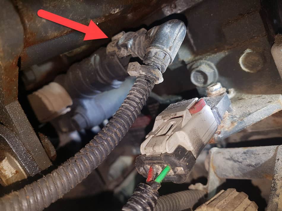
Many off-highway machines also have protective covers on the plug housing, making our inspection even more difficult.
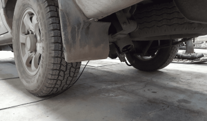
Question 2: Engine speed. The crankshaft position sensor was also in a difficult position, as we needed to remove the cover from underneath the machine. Making any connections requires running a test lead through the belt, something I don't intend to do, fortunately the crankshaft position sensor has its gearing on the belt pulley, so all I need to do is create a sensor that will allow me to get a signal.
Take the keyless entry probe (TA330), and the magnet. This is not an ideal solution, and I have not yet calculated the limits of the TA330. By connecting the magnet to the external body and positioning it in the area of the belt teeth of the crankshaft pulley, I managed to obtain the following catches.
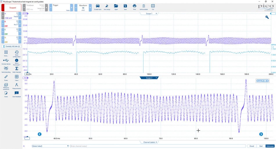
Not bad considering it's my own creation by the way! Calculating the mathematical channels of the crankshaft requires more resolution, and some improvements to the magnet positions might help.
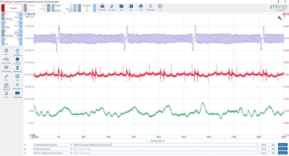
- Channel A: Crankshaft Belt Plate Signal
- Channel B: Oil Rail Pressure Sensor
- Channel C: Exhaust pulse
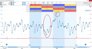
The capture above was taken with the engine idling and no load. As you can see, the fuel pressure looks unstable, but the focus here is on the exhaust pulse. Normally we would expect a nice even waveform, but it's not stable on this machine.
By applying engine loads and looking at the screen, we can begin to see a pattern emerging.
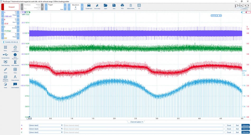
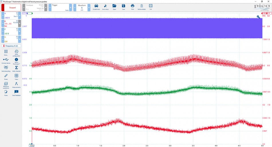
- Channel A: MAF Perceptron
- Channel B: Intake manifold pressure value
- Channel C: Oil Rail Pressure Sensor
- At the bottom is the frequency math channel for the crankshaft.
We can see that the rail pressure reacts to the reduced engine speed and is controlled. This means that fuel is not our concern. Therefore, we must move to the air system in the combustion chamber.
Going back to the string data available on the screen, we look at MAF, EGR, and boost pressure. When the machine is at idle and under load, all the expected and actual data are the same. However, there is an interesting choice of units for the MAF in kg/s. I don't think this will help us when the engine is running because the value doesn't change much, in fact it will definitely change as the engine speed changes.
We have a luxury identical machine with the same engine and no faults. When we compared the actual data between the two, they were almost identical. We found that it was no longer possible to get this information using the MAP sensor, meaning we had to use the WPS500X to check. Luckily, it had a hole in the intake manifold that, to our surprise, allowed us to install the Mars Plug Adapter that comes with the WPS500X kit! This meant we were able to see the MAF, rail pressure and intake manifold pressure, the MAF sensor is a digital signal sensor but is inverted as seen on some PSA vehicles. With the built-in frequency math channel, we can easily plot it with the other channels.
- Channel A: MAF Perceptron
- Channel B: WPS500X Measurement Air Inlet Manifold
- Channel C: Oil Rail Pressure Sensor
- Frequency math channel at the bottom
When looking at the frequency math channel of the MAF perceptron, we must keep in mind that it works the opposite way you would expect. The faster the air, the lower the frequency. From this we can see that the rail pressure is the same as the intake pressure and airflow pattern.
Tech Tip: To invert any math channel, you can place a minus sign in front of the channel letter.
For example, to invert the frequency math channel above, enter freq(-A).
When connecting the MAF to the intake manifold, I kept the lines on top of the machine to make sure they were connected and that the WPS500X adapter would not pop out of the manifold. When loading the machine, I heard some sounds that I don't normally hear.
When you hear this audio, you should be able to hear the air impingement when the machine is loaded, which can mean one thing. Namely a hole in the pressurized side of the intake. As mentioned above, you can't hear the sound when standing on the ground or in the cockpit.
Along with this sound, we found that the MAF Perceptor housing had ground a hole in the boost tube from the turbocharger tube to the intercooler.
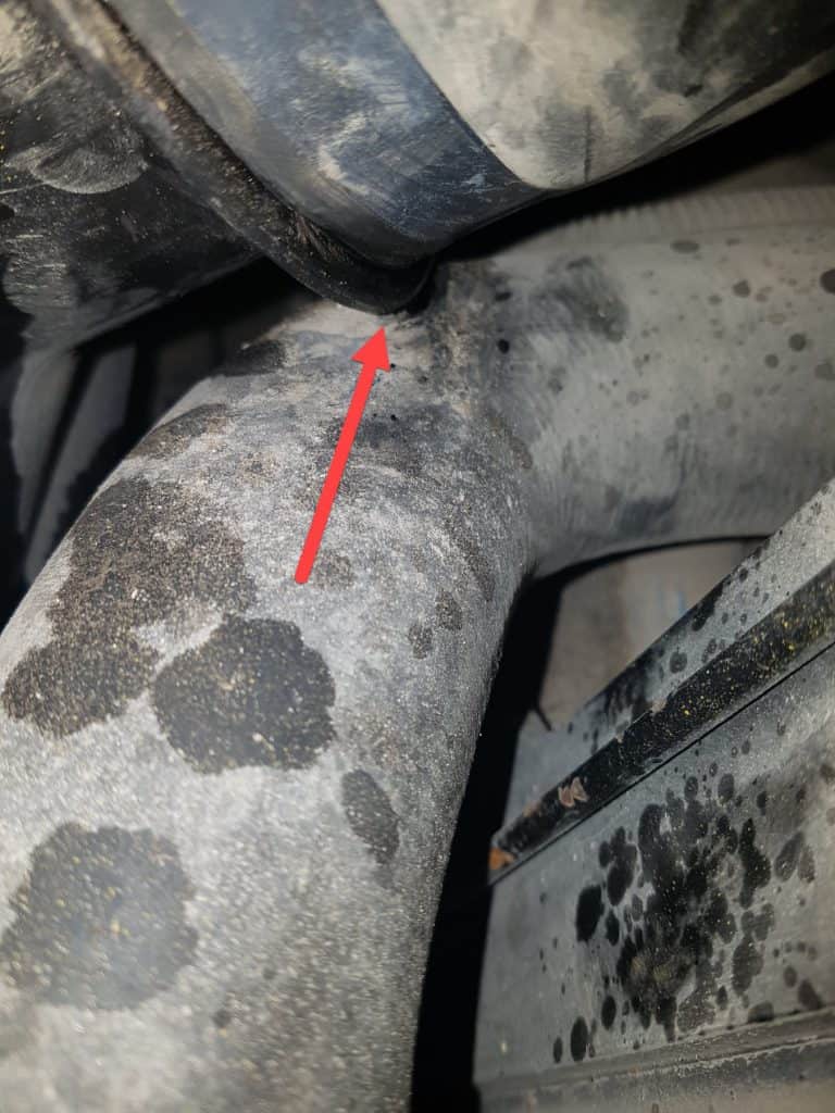
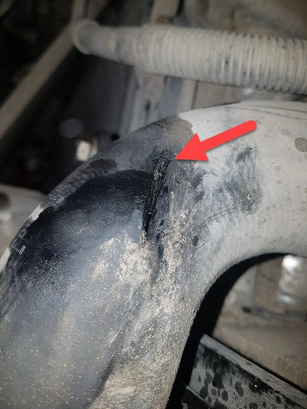
This appears to be a design flaw in the MAF housing which has worn through the tubing over time. Due to the location of the pipe, the normal noise of the machine is not audible during operation.
Although I was convinced that this was the problem, we made a temporary repair to this part and loaded the engine as we had done before to verify that replacing the line would solve the problem.
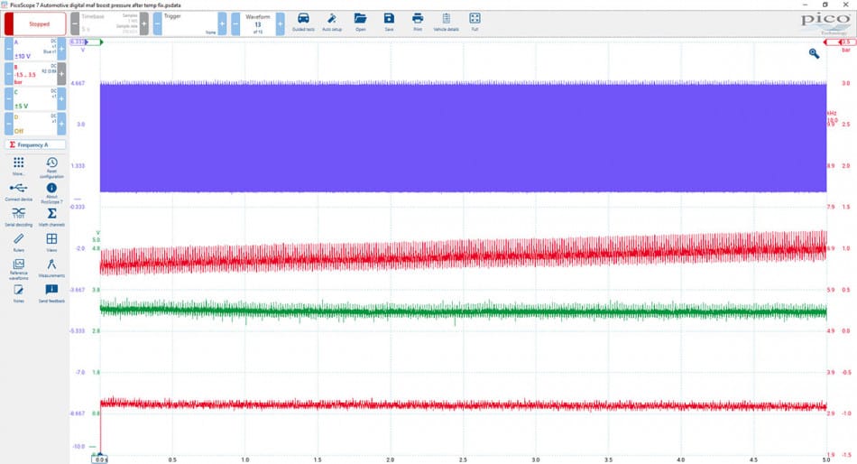
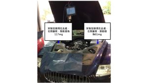
By using the same time base, we can make a comparison. In the capture above, we can see that the intake manifold pressure continues to rise throughout the buffer zone, eventually reaching 1 bar.
Compared to the previous figures the boost pressure did not reach 1bar and dropped to 0.5bar before the succeeding climb, the engine no longer shakes and although there is some black smoke it is not as bad as it was before the temporary fix.
We wondered why the problem only became apparent after the engine was warmed up. One theory is that the rubber hose hardens over time and this rigidity allows pressure to build up as the rubber cools. As the engine and air temperatures warm the tubes, the rubber becomes softer, which in turn makes the holes larger and causes a drop in pressure. As the engine speed drops, the boost pressure drops, so the holes reseal and pressure builds up again and the cycle repeats. This is just a theory, if you guys have any other ideas, feel free to share them, I'd be interested in hearing them.
Faults like this can be very disorienting, especially if you can't find any obvious faults. By using an oscilloscope, we can visualize the signals from the sensors to find their relationship. I'm sure some of you may have gone down the smoke test route, but I'm not sure if he's going to show the amount of pressure that has to be generated and where the notch is located. I have limited knowledge of the smoke test and am not sure if it is designed to be pressurized to that pressure, but would be happy to learn that part of the story.
Thank you to Roy Sturges of RCT Power Services for inviting me to participate in this diagnostic adventure.