A simple intro to CAN errors
CAN bus error
In this series of articles, we will introduce you to the details of the CAN bus errorThe knowledge includes the basic concepts of CAN Bus Errors, types of CAN Bus Errors, CAN Error Frames, and CAN Node Error States, as well as generating and documenting CAN errors through practical application testing.
What is CAN bus error?
Controller Area Network (CAN) is an important standard in today's automotive and industrial automation systems. Reliability is one of the core strengths of the CAN bus protocol, making it ideal for safety-critical applications.However, it is worth noting that error handling is crucial for the robustness of CAN.
CAN bus errors can occur for a variety of reasons, such as cable failures, noise, mismatched terminal resistors, CAN node failures, and more. Identifying, categorizing, and resolving such CAN errors is critical to ensuring the enduring performance of the entire CAN system. Error handling identifies and rejects erroneous messages, allowing the sender to retransmit the message. In addition, the process helps to identify and disconnect CAN nodes that are continuously transmitting erroneous messages.

How CAN Error Handling Works
Error handling is built into the CAN standard and every CAN controller. In other words, each CAN node handles fault identification and limiting in the same way. A simple illustrative example is shown below:
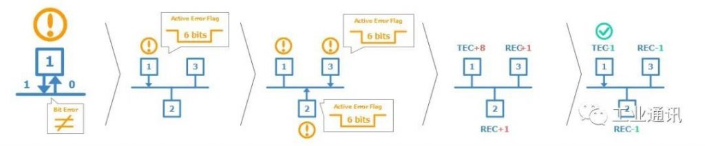
Examples of Specific Steps
- CAN node 1 transmits the message to the CAN bus-and reads every bit it sends; in doing so, it finds that the bit sent explicitly is read implicitly.
- This is a “bit error” where node 1 triggers an active error flag to notify the other nodes, which in effect means that node 1 sends a sequence of 6 dominant bits to the bus, and in turn, the 6 dominant bits are seen by the other nodes as a “bit-fill error”
- In response, nodes 2 and 3 both trigger an active error flag, and this sequence of triggered error flags forms part of the “CAN error frame”.
- CAN node 1“s transmitter increases its Transmit Error Counter (TEC) by 8, CAN nodes 2 and 3 increase their Receive Error Counter (REC) by 1, and CAN node 1 automatically retransmits the message. As a result, node 1 decreases its TEC by 1, and nodes 2 and 3 decrease their REC by 1.
CAN error frame
In the above example, the CAN node “triggers an active error flag”, which creates an “error frame” in response to the detected CAN error. To understand how this works, let's first look at a “normal” CAN frame (no errors):
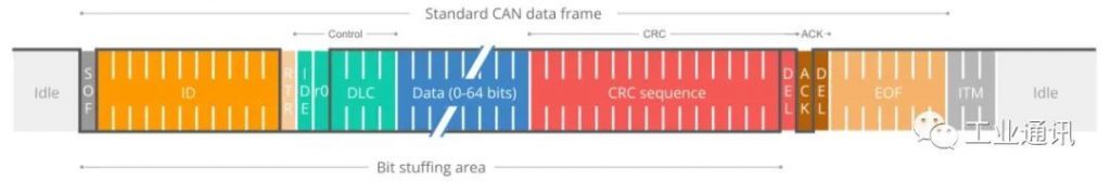
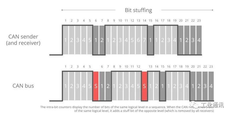
Note that we have highlighted “Bit Fill” in the CAN frame. Bit padding is a subtle but important part of the CAN standard. Basically it states that whenever a CAN node sends five bits of the same logical level (explicit or implicit), it must send one bit of the opposite level. The receiving CAN node automatically deletes this extra bit. This process helps to ensure continuous synchronization of the network.
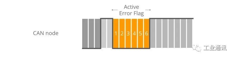
According to the previous example, when CAN node 1 detects an error during a CAN message transmission, it immediately transmits a 6-bit sequence of the same logic level - also known as the triggering activity error flag.
As mentioned earlier, such a sequence violates the bit-fill rule - also known as a “bit-fill error”. In addition, this error is visible to all CAN nodes on the network (as opposed to the “bit error” that caused this error flag to appear). Therefore, the addition of the error flag can be seen as a way of “global” error detection, ensuring that every CAN node is notified.
Note that other CAN nodes treat the active error flag as a bit-fill error. In response, they will also raise an active error flag. As we will explain later, it is important to distinguish between error flags. In particular, the first error flag (from the “Discovery” node) is usually called the “Primary” activity error flag, while the subsequent error flags from the “Response” node are called the “secondary” activity error flag(s).
CAN Error Frame Example
Example 1, 6-bit Log Error
Here, all CAN nodes simultaneously find an error in the CAN telegram and issue an error flag at the same time. The result is that the error flags all overlap and the total sequence of significant bits continues for a total of 6 bits. In this case, all CAN nodes consider themselves as “discovered” CAN nodes.
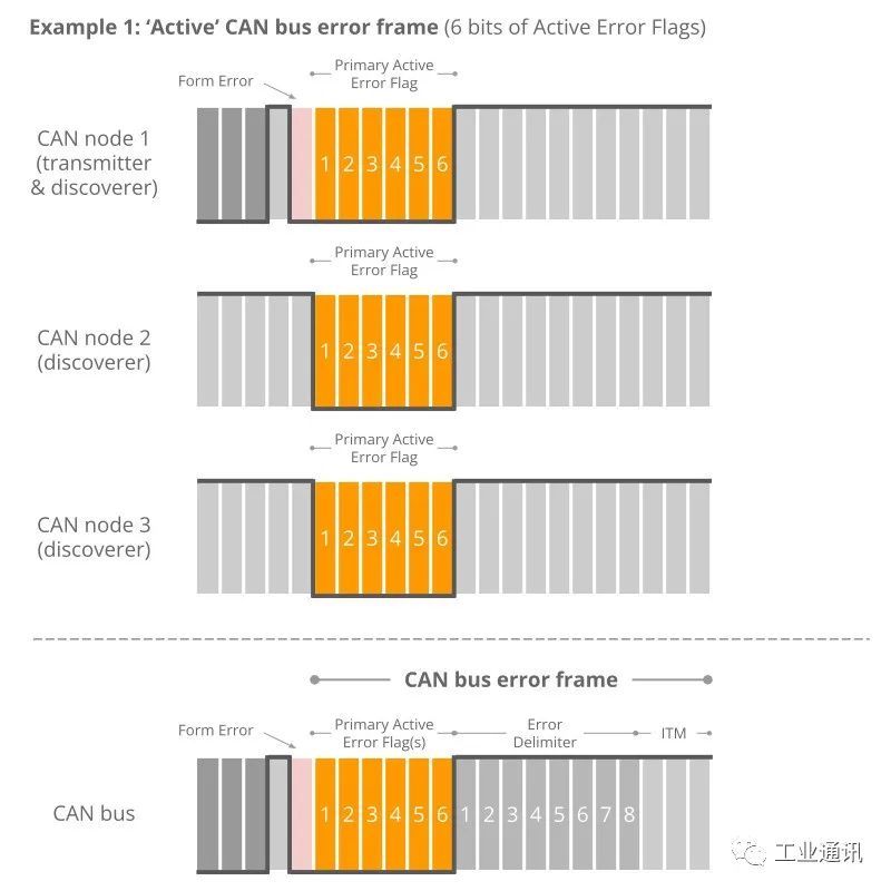
It was also found that this type of error frame is not very common in practice. However, it may occur due to a formatting error (e.g., the CRC delimiter is explicit rather than implicit) or a bit error encountered by the CAN transmitter during the write of the CRC field.
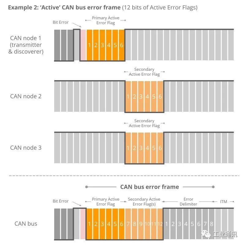
Example 2, 12-bit Error Signs
In this example, CAN node 1 transmits a dominant bit, but reads it as a recessive-which means it finds a bit error. It immediately sends a sequence of 6 significant bits. The other nodes discover the bit-fill error only after reading the full 6 bits, and then they simultaneously raise the error flag to generate a sequence of the next 6 dominant bits-that is, 12 in total.
Example 3, 9-digit error code
In this example, when CAN node 1 recognizes the bit error and starts sending 6 dominant bits, it has already sent 3 dominant bit sequences. Once halfway through the main event error flag, nodes 2 and 3 recognize the bit-fill error (due to the 3 initial dominant bits followed by the other 3 dominant bits) and begin raising their error flags. The result is that the sequence of dominant bits from the error flag becomes 9 bits long.
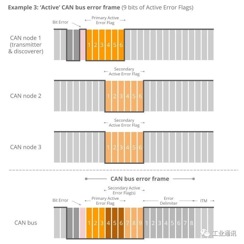
The above logic for triggering error flags is reflected in what we call “active” CAN error frames. Note in particular how the secondary error flags triggered by each node overlap each other - and how the primary and secondary flags may also overlap. The result is that the primary bit sequence from which the error flag is triggered may be 6 to 12 bits long.
The sequence is always terminated by a sequence of 8 hidden bits that mark the end of the error frame. In practice, the active error frame may “start” at a different position in the wrong CAN frame, depending on when the error is detected. However, the result will be the same: all nodes discard the erroneous CAN frame, and the sending node can attempt to retransmit the failed message.
Passive error flag
If a CAN node has changed from its default “active” state to “passive”, it will only trigger the so-called “passive error flag”. The passive error flag is a sequence of 6 implicit bits. In this case, it is relevant to distinguish between passive error flags triggered by the sending node and the receiving node.
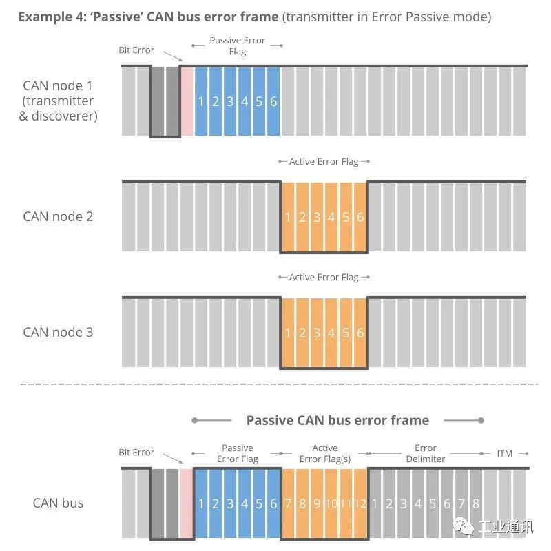
Example 4, Transmitter is a passive error.
As shown in the figure, if a transmitter (e.g. CAN node 1 in our example) triggers a passive error flag (e.g. Response Bit Error), this corresponds to a continuous sequence of 6 hidden bits. This in turn is detected as a bit-fill error by all CAN nodes. Assuming that the other CAN nodes are still active with their errors, they will trigger an active error flag for the 6 dominant bits. In other words, the passive transmitter can still “communicate” that the CAN frame is wrong.
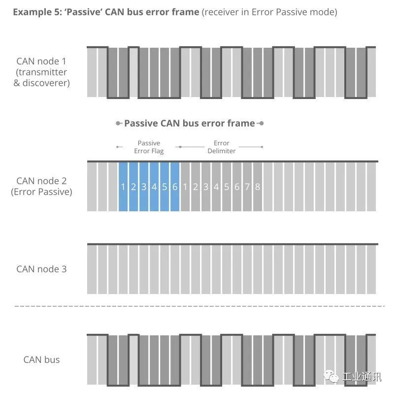
Example 5, Receiver is Active Error
Conversely, if the receiver generates a passive error flag, this is effectively “invisible” to all other CAN nodes on the bus (since any dominant bit is better than a sequence of recessive bits). In practice, this means that the error passive receiver no longer has the ability to corrupt frames transmitted by other CAN nodes.
~Follow us to get more technical knowledge.
Honghong Electronics provides hardware devices such as CAN cards, CAN data loggers, data acquisition modules, CAN gateways and converters, as well as software such as the Kvaser CANLIB SDK.Deep technical accumulation and excellent technical service ability is the reason why many customers choose Hongke, welcome to contact us at any time!