With the rise of global IR cameras, each wavelength has reached a certain function in different industries, such as short-wave red, which is being used in the automotive field with the rise of ADAS, and medium-infrared, which stabilizes the development of optical components.
This article introduces the CLAMIR Laser Power Closed Loop Control SystemIt is one of them, integrating VPD PbSe infrared camera and mid-infrared technology with embedded real-time computing system, and realizes high-quality and sustainable process by continuously controlling the laser work to avoid localized overheating in the process.
Let's take a look at the CLAMIR system...
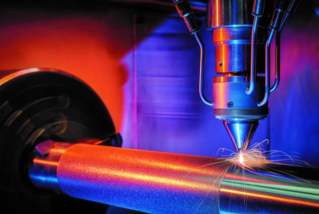
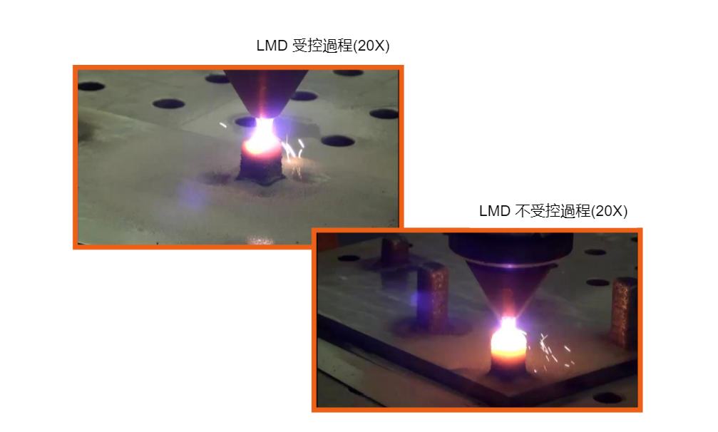
LMD Processing with CLAMIR System
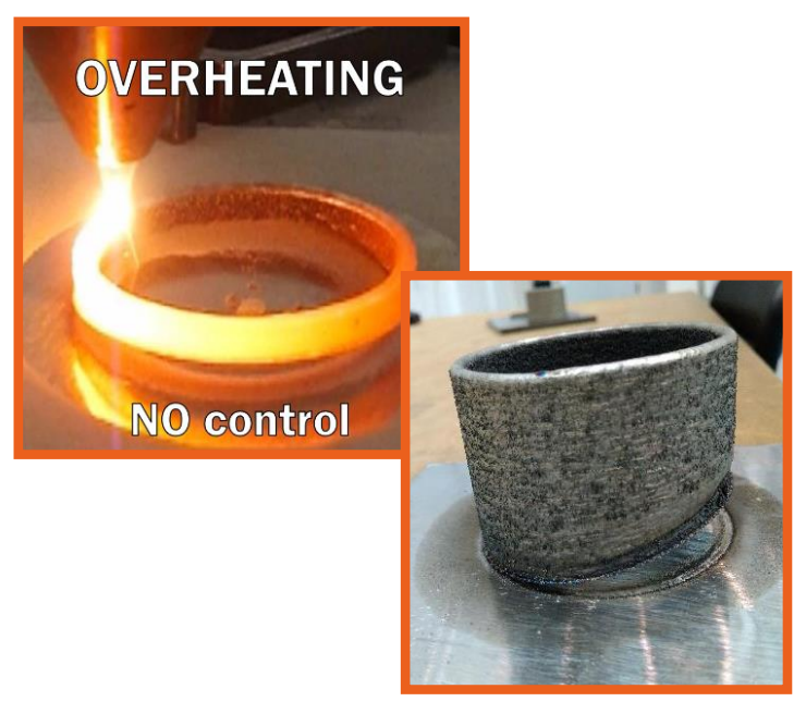
The continuous control of the laser avoids overheating of the parts during machining and allows a continuous and high quality machining process.
The use of CLAMIR reduces the ratio of defective parts, material used and energy compared to uncontrolled processes. It can also help optimize processes and increase productivity.
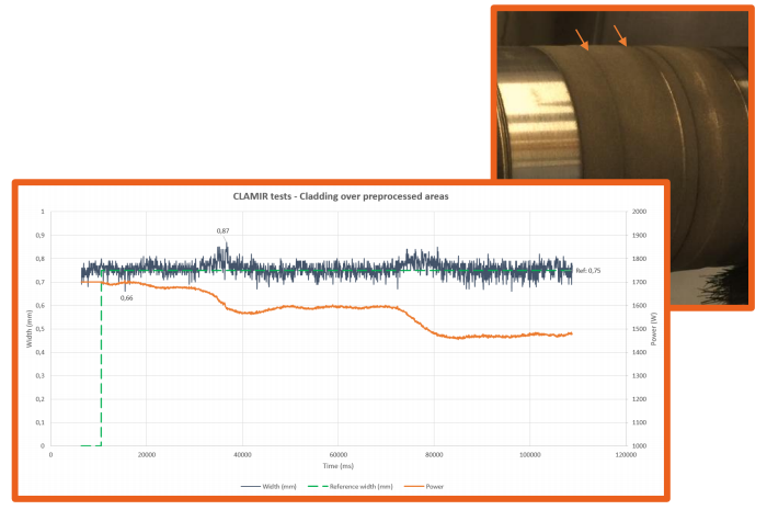
Application of the CLAMIR system in the cladding process
Continuously controlled laser power allows for large area/long continuous processing
The use of CLAMIR reduces the dilution rate and damage to the substrate caused by excessive laser power.
CLAMIR System Purpose
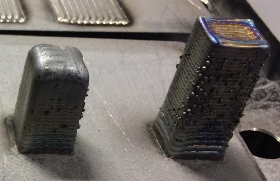
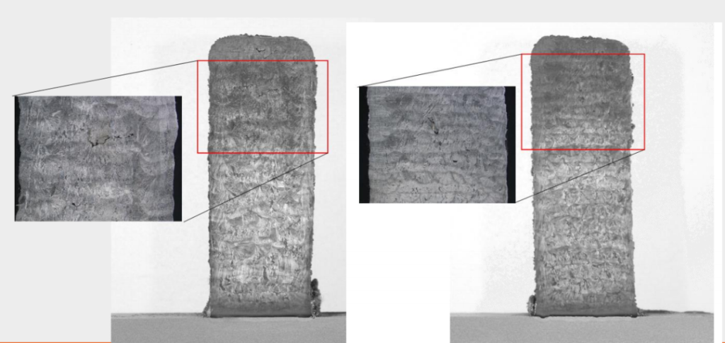
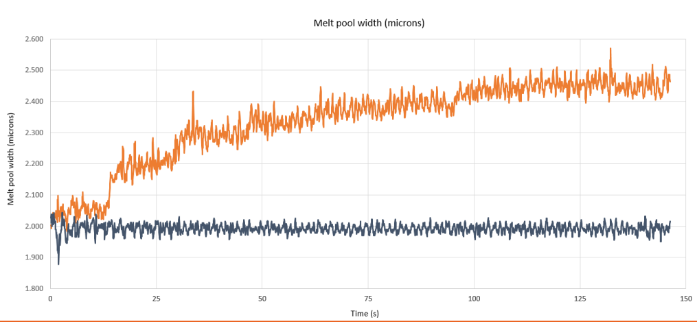
Uncontrolled constant laser power during the LMD process can lead to unstable, non-repeatable processes and poor quality or defective production parts.
To ensure that the machine produces high-quality parts efficiently, the laser power needs to be controlled continuously and in real time throughout the process.
○Needs a simple system that is fully integrated with the laser optics system.
Key Features
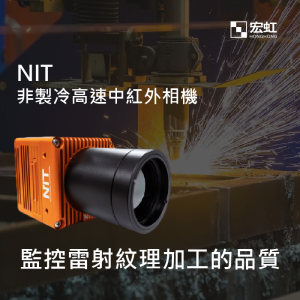
o Continuous monitoring and measurement of melt pool geometry using MWIR infrared camera (1.1 um - 5.0 um)
Closed-loop control of laser power throughout the process to ensure quality and repeatability.
○Compatible with most laser optics and powders
○Easy mechanical integration and fast configuration
o Consistent operation, no need to reconfigure during the process
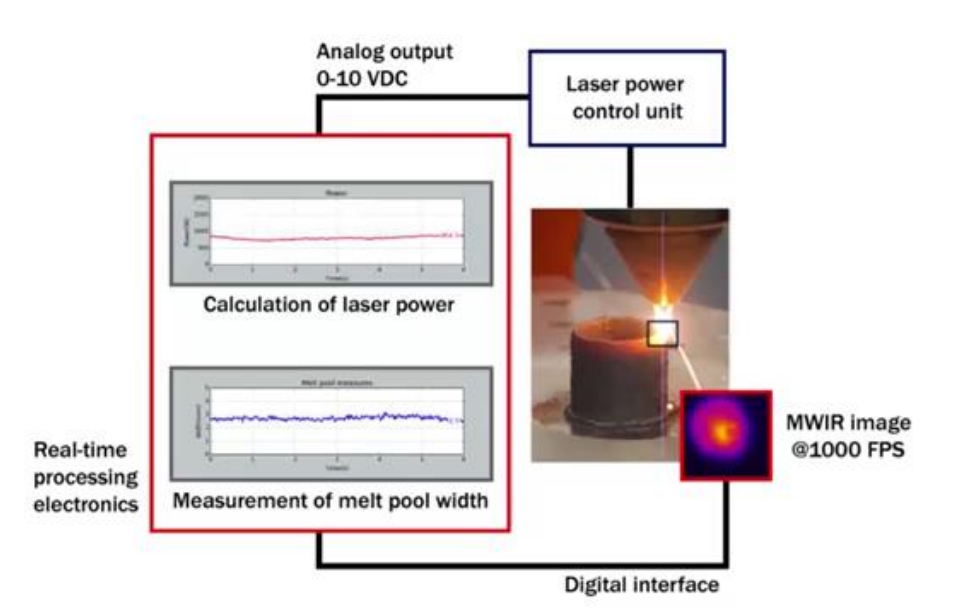
Working Principle
Continuous monitoring of melt pool geometry using high speed MWIR infrared camera (1.1um-5.0um)
Embedded electronic processing equipment for real-time dimensional measurement of the melt pool.
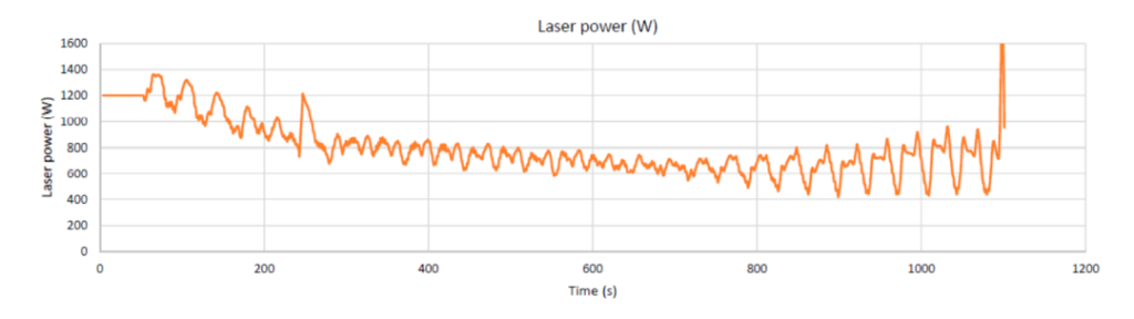
Calculate and control optimal laser power via analog output (0VDC-10VDC).
Technical Advantages
Advantages over CMOS-based solutions:
- Wider temperature detection range (+100ºC)
- Higher precision
- High power, high strength signal and sputtering reliability
- Wider dynamic range
Advantages compared to solutions based on high-temperature measurements:
- Image Processing Technology vs Single Point Measurement
- Requires 2-color thermometer for accurate temperature readings
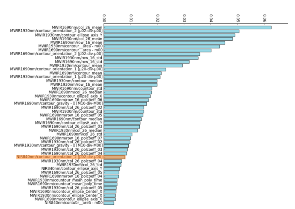
46 best tests based on 40 features extracted from two MWIR (PbSe) acquired images, and a visible-close-infrared (CMOS) sensor observing the same weld trajectory.
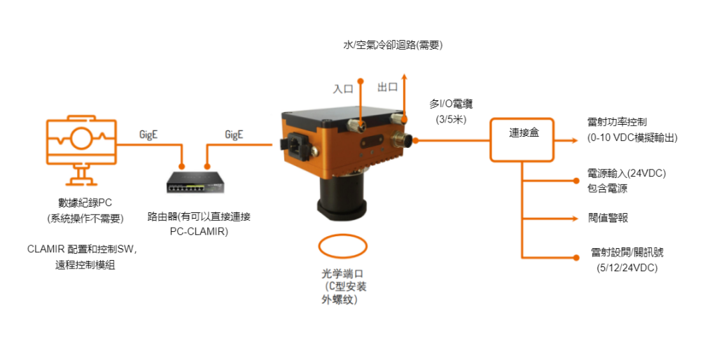
System Introduction
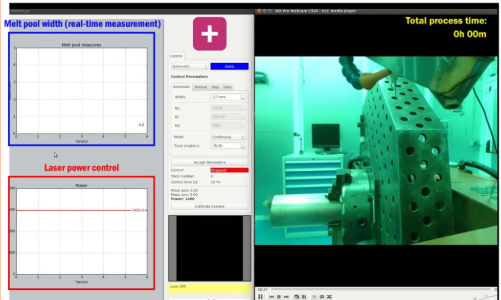
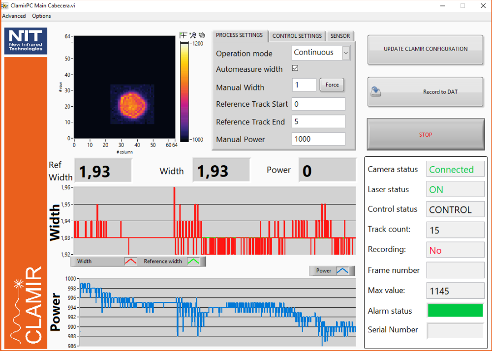
System components: SW (configuration and control, visualization)
○ Desktop applications for configuration and data logging (not required for CLAMIR operations)
Allows configuration of process parameters (laser power range) and closed-loop feedback control.
○Other functions: operation mode selection, camera control, ROI definition (round, square)
○Data file visualization and analysis
○ DLL for custom S/W development (coming soon)
Mechanical Integration Program
○On-axis optical system integration to monitor melt pool geometry
○ Infrared transmission (> 1.1 um) required for laser head optical paths
○Integration into the laser head using existing optical ports
○Easy mechanical integration and fast configuration
Dichroic mirror compatible with existing VIS cameras for alignment and process visualization
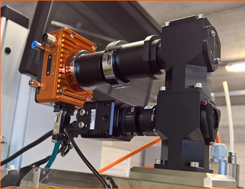
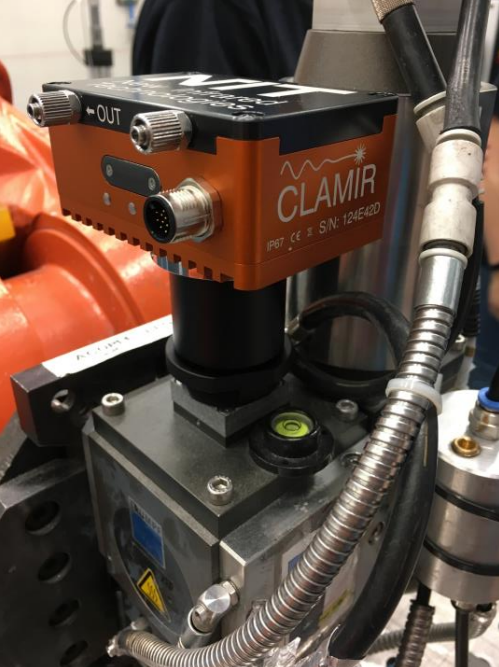
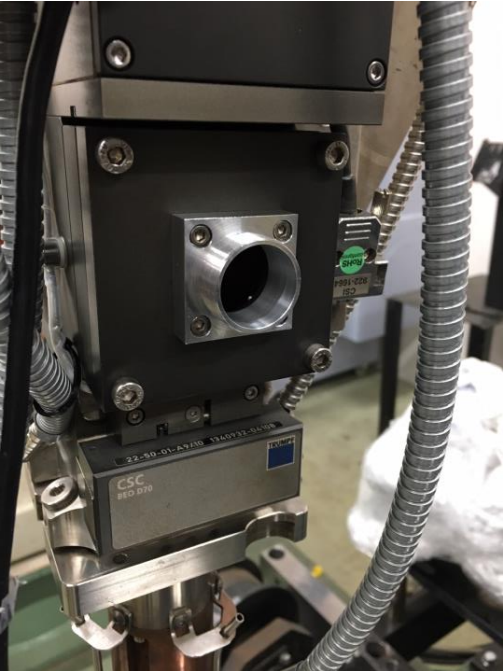
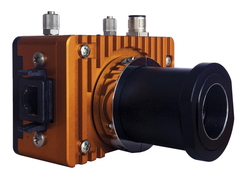
Install the coupling component in the optical port (photo shows coupling to a TRUMPF BEO-D70 as an example; CLAMIR is compatible with other brands of laser optics). (center)
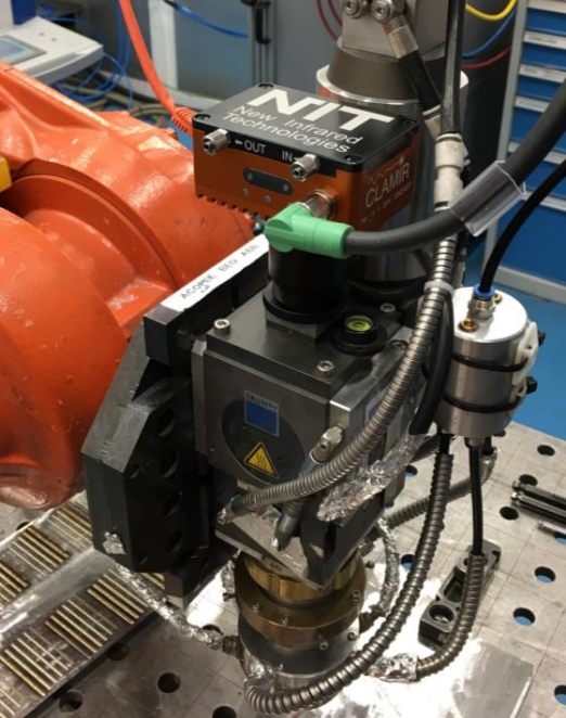
The CLAMIR is mounted in the laser optics system by screwing the front of the lens into a coupling component. (left)
Connect the supplied multi-I/O cable and chilled water hose. (Optional) Connect to Ethernet (not required for operation). (Right)
Want to know more about our products? Welcome to contact us
More Industrial Cameras >>>Click on me to enter