ralph lauren overview
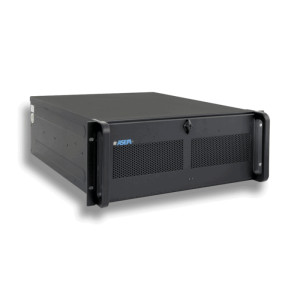
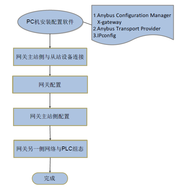
When one side of the Anybus X-gateway gateway is used as EtherNet/IP master and the other side is used as slave, the configuration process is shown in Figure 1-1. This article mainly introduces the configuration process of the gateway and the configuration of the master side of the gateway. In this article, we take the gateway AB7669 as an example, one side of the network is EtherNet/IP Scanner/Master, and the other side of the network is Modbus-TCP Slave. if the slave side is another network, the configuration process is similar.
ralph lauren polo shirts
The AB7669 interface definition is shown in Figure 2-1; the hardware connection schematic is shown in Figure 2-2.
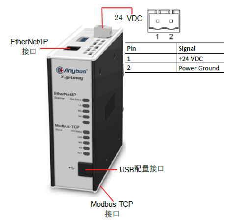
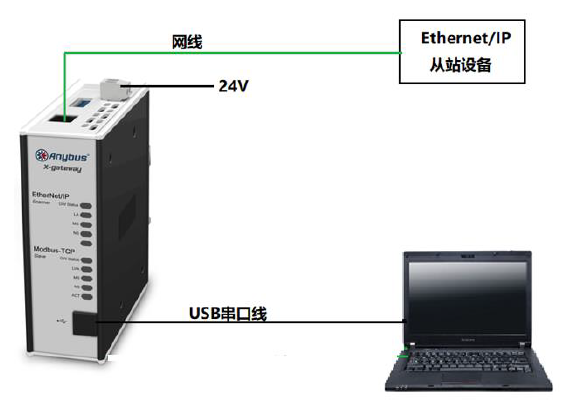
Figure 2-2 Hardware Connection Schematic Diagram
ralph lauren polo ralph lauren polo shirt
Software that needs to be installed on a PC:
- Gateway configuration software:
- Drive:
- IP address configuration software:
ralph lauren gateway configuration description
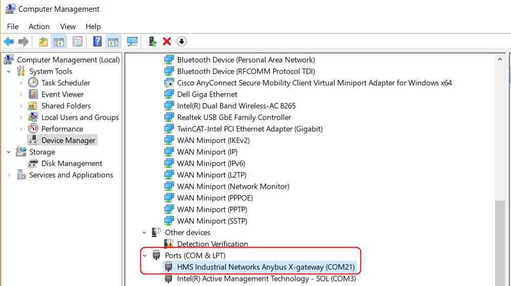
Check the port number of the USB cable. Check the port number of the USB download cable that connects the PC to the gateway in My Computer, as shown in Figure 2-3, the port number is COM21.
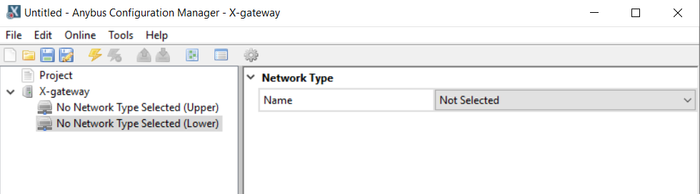
2. Double click Anybus Configuration Manager- X-gateway to open the interface shown in Figure 2-4. During the configuration process, it is recommended to upload the configuration information of the gateway first, and then modify the parameter information such as the number of input and output bytes or the control status words according to the actual situation, so as to avoid the wrong selection of both sides of the network. Each Anybus X-gateway gateway is configured by default at the factory with 20 bytes of output and 20 bytes of input.
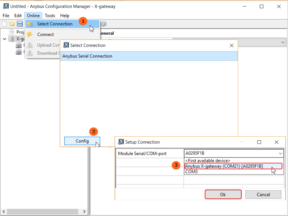
- Select Connection Port: Click “Online” in the menu bar of the configuration tool interface, click “Select Connection” in the drop-down menu, and then click the “Config” button in the pop-up dialog box. Config“ button in the pop-up dialog box, in the pop-up dialog box, select ”Anybus X-gateway(COM21)[A0295F1B]“ option in the drop-down menu, and finally click ”OK" to confirm. Click "OK" to confirm, as shown in Figure 2-5.
4. Connect: Click the Connect button in the shortcut to establish a connection. If the connection is established the Connect button will be grayed out and the Disconnect button next to it will be highlighted.
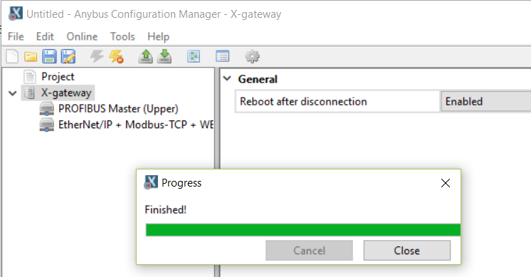
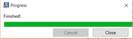
5. Upload Configuration Information: Click the Upload Configuration from Device button in the shortcut to upload the configuration information in the gateway, and then click the “Close” button in the progress bar when the upload is completed, as shown in Figure 2-6.
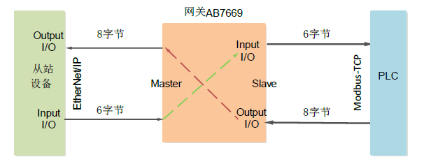
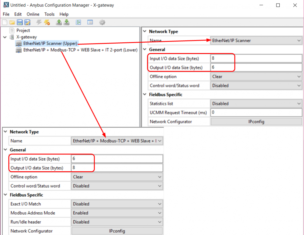
6. Modify the corresponding parameters after obtaining the uploaded configuration information, mainly modify the number of input and output bytes, other parameters can be kept in the default settings. Since the total input of the slave device on the Ethernet/IP side is 6 bytes, and the total output is 8 bytes, according to the working principle of the gateway, the input configuration on the Ethernet/IP Scanner side is 8 bytes, and the output configuration is 6 bytes, and the input configuration on the Modbus-TCP side is 6 bytes, and the output is 8 bytes, and the other parameters can be kept in the preset settings, as shown in Fig. 2-7. 7 shows.
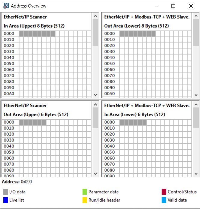
7. Check the data memory allocation. Click “Tools” in the menu bar and select “Address Overview” in the drop-down menu to bring up the memory address usage, as shown in Figure 2-8.
8. Click the Download button in the shortcut to download the configuration information to the gateway, and then click the Close button on the progress bar when finished.
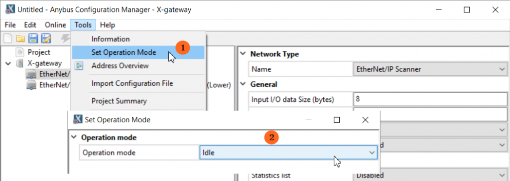
9. Click “Tools” in the menu bar and select “Set Operation Mode” in the drop-down menu, in the pop-up dialog box, switch the gateway operation mode to “Idle” mode, as shown in Figure 2-10. In the pop-up dialog box, switch the gateway operation mode to "Idle" mode, as shown in Figure 2-10. Note: You must switch the gateway to Idle mode, otherwise the gateway cannot configure the network on the master side when it is in operation mode.
ralph lauren polo gateway master side configuration description
Configuration on the master side of the gateway is done through Internet Explorer.
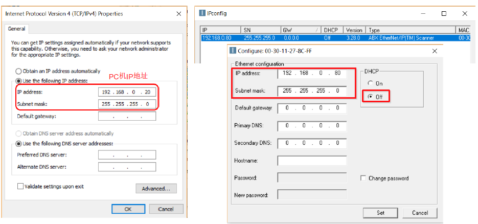
- Use a network cable to connect the EtherNet/IP interface of the PC to the gateway AB7669. Open the IPConfig software, double-click the network scanned by ABX EtherNet/IP(TM) Scanner, and set the IP address of the gateway's EtherNet/IP network to be on the same network segment as the PC's IP address in the pop-up dialog box, as shown in Figure 2-11.
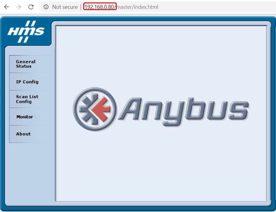
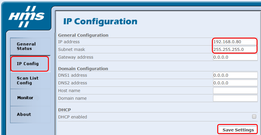
2. Open Internet Explorer and enter the IP address of the AB7669 EtherNet/IP port. Enter the address 192.168.0.80 as shown in Figure 2-11, and the interface will be displayed as shown in Figure 2-12.
3. Click the “IP Config” button in the left list to modify the IP address of the EtherNet/IP port, and then click the “Save settings” button to save the settings. If you don't need to change the IP address, you can skip this step directly.
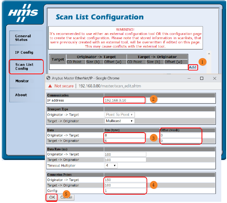
4. Click the “Scan List Config” button in the left list to add the slave device information. As shown in Figure 2-14.
❶ Click the “Add” button on the screen.
❷ Enter the IP address of the EtherNet/IP slave device in the pop-up dialog box “IP address”.
❸ In “Data”, input the number of input and output bytes of the slave device (Originator -> Target: output, Target -> Originator: input), the unit is byte; in “Offset In ”Offset", enter the offset word, the offset address of the data storage, starting from 0. When there are several devices, the offset address needs to be calculated according to the number of input and output bytes of the previous device, the unit is word.
❹ Fill in the Connection Points with the slave equipment manufacturer's example number to view its EDS file or contact the slave equipment manufacturer to obtain it.
❺ Click “OK” to finish. Repeat the above operation if you have more than one slave device.
Note: The IP address of the slave device should be in the same network segment as the IP address of the gateway EtherNet/IP port.
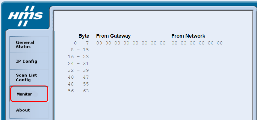
5. Click the “Monitor” button in the left list to monitor the online data.
6. Configuration is complete, since the gateway is in Idle state, you need to power off and reboot the gateway.
Contact Us