preamble
ADC static parameter testing plays a key role in high-speed communication, medical imaging and automation applications. This article analyzes the definition of ADC transition point, test logic, and introducesAcer TS-ATX7006 and TS-ATView7006 Systemsapplication, and describes theCritical Point Search and Code Sorting MethodsTwo ways to effectively improve analysis accuracy and efficiency.
Analog-to-digital converters (ADCs) and digital-to-analog converters (DACs) play a critical role in the design of modern electronic systems and in high-speed communications, signal processing, radar detection, medical imaging, and various industrial automation applications. ADCs convert analog signals to digital signals precisely and efficiently for digital signal processing and data transfer, while DACs perform the opposite function by reducing the digital data stream to a high-quality analog signal for use in the actual device or system.。
As technology continues to advance, especially for the demanding requirements of 5G communications, aerospace, and defense, high-speed, high-precision, high-resolution, and wide dynamic range ADCs and DACs are becoming increasingly important. In order to explore the basic performance indicators of these critical components, MAXTRON will guide you into the world of static parametric testing of ADCs and DACs. In this article, we will introduce you to a key concept in ADCs - the transition point.
Introduction
The linear parameter calculations (INLE, DNLE, etc.) of the A/D converter are based on the change point (or critical point) of the device. To determine the change point of the ADC, theAdequate step sizeThe simulated ramp characterizes the post-absorption input of the component. The change point can be determined from the measured output value.

Calculation of Linear Parameters of A/D Converters
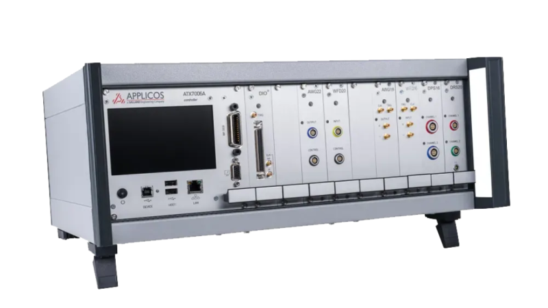
There are two ways to determine the trip point for the ATEN ADC test system TS-ATX7006 and software TS-ATView7006:
- Variable Point Search Method: The algorithm "searches" for jump points. Consider the position of the measurement output in the result array.
- Code Sorting Method: The number of times the program code appears in the result array is a measure of the LSB step size.
Variable Search Method
To search for the threshold from output value x to output value x+1 (x -> x+1), first search for the first occurrence of output value x in the data array and the last occurrence of output value x+1 in the data array, which is the search array for the jump point.
The output value x and the number of occurrences less than the output value x are counted in the area. The jump point is at the location where the output value x plus the counter value (the number of times the output value x and fewer output values are found in the area) is found for the first time.
The missing program code at the beginning and end will be estimated by the ideal converter step (DNLE=0), using the first jump point found as a reference. Finally, theThe jump points are estimated from the last jump point found.. All other missing codes result in a DNLE of -1: the jump point is in the same position as its predecessor.
Noise or insufficient measurement resolution may cause the DNLE to be less than 1 LSB.
Scenario 1: No noise
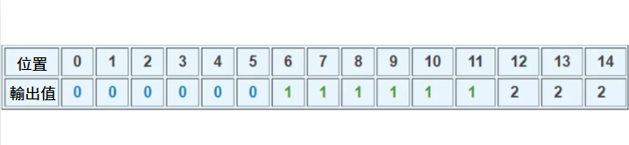
Captured Digital Data Arrays
Jump point 0→1.
Search Range: Position 0-11.
Count: 6
The trip points are located in positions 5 to 6. the trip point voltages are: Vtrp=Vstart+count*Vstep-1/2Vstep
Among them:
Vstart = Start voltage of the supplied ramp.
startposition=The position where the code was first found, in this case position 0.
count = number of times the output value 0 is found
Vstep = Voltage step of the supplied ramp.
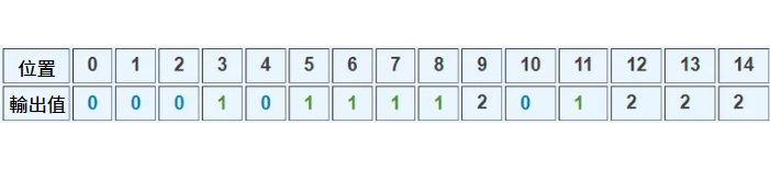
Scenario 2: Noise
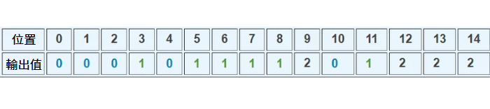
Captured Digital Data Arrays
Jump point 0→1.
Search Range: Position 0-11.
Count: 5
The jump point is located at position 4 to 5.
Jump Point 1 → 2.
Search range: Position 3-14.
Count: 8 (6 outputs of value 1 + 2 outputs of value 0)
The jump point is located at position 10 to 11.
Scenario 3: Loss of Output Value
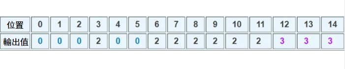
Captured Digital Data Arrays
Captured digital data arrays:
Jump points 0→1 and 0→2.
Search Range: Position 0-11.
Count: 5
Both jump points are located at positions 4 to 5.
Code Sorting Method
All output values are sorted in the data array. After sorting, the data array starts with all measurement output values 0, then output value 1, and so on. Therefore, the position of the output values in the measurement data is irrelevant. DNL errors of less than -1 do not occur using the sort code method.
typical example
Array of numeric data captured before sorting
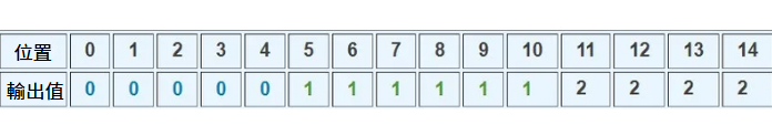
Array of Sorted Retrieved Numbers Data
Learn more about our products
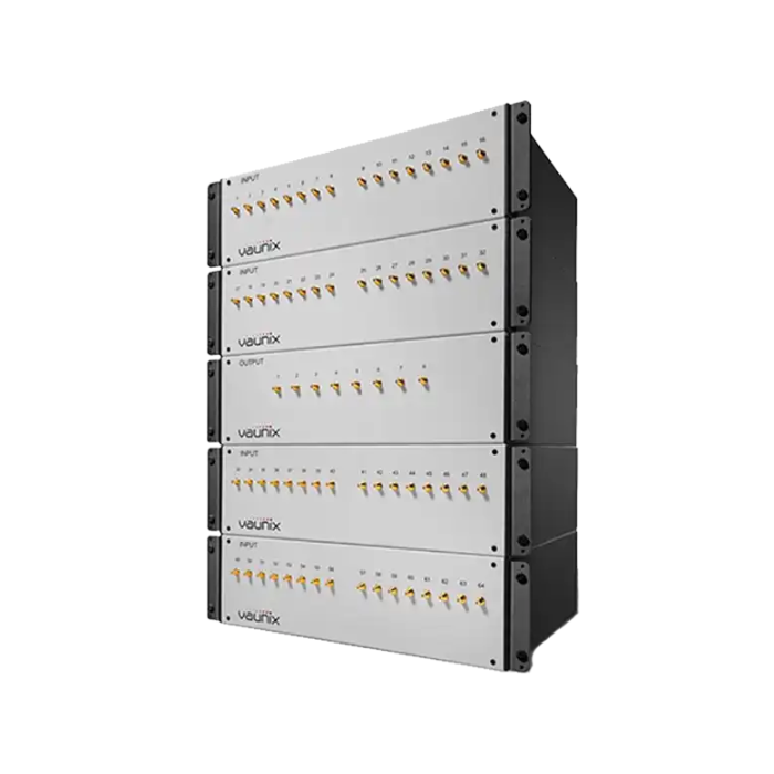
Vaunix Digital Matrix Attenuator - Efficient 5G and WiFi Wireless Switching Test Solution
●VAUNIX Digital Attenuator Matrix as Wireless Switching Test System
●Bringing Economy, Functionality, Reliability and Simplicity to Microwave Test Stations
● Vaunix Attenuator Ideal for a Variety of Complex 5G, WiFi and Satcom Module Testing Needs
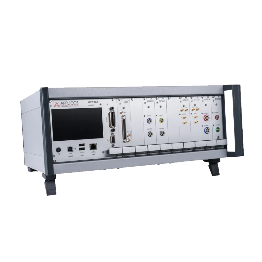
ADC/DAC Test System
9-slot ATE wafer test platform with modular design for flexibility and scalability
DIO clock synchronization module for 8-24 bit ADC/DAC measurement.
● Sampling rate of up to 400 MHz sets a new standard for efficient wafer testing
If you are interested, you are welcome to follow us for more information about the article and contact us if you have any questions!