
Industrial Raspberry Pi is a Raspberry Pi based industrial grade industrial controller product with a full range of models and features, including fieldbus protocol gateway ratio and DIO, AIO and other module extensions.
The Industrial Raspberry Pi is industrial ready, with an operating temperature range of -40 ~55 °C, ESD protection up to 4 kV / 8 kV, and surge/burst testing and EMI testing to EN61131-2 and IEC 61000-6-2 standards. Supports multiple programming languages such as Node-RED, Python, or pure C. Supports common Industrial Internet of Things (IIoT) protocols such as MQTT and OPC UA. Contains two Ethernet interfaces, one of which can connect to an industrial field network via the Modbus TCP protocol, and the other can be connected to a higher-level IT system or a cloud server.
ralph lauren preface
In this paper, we will use Python to program and read the values of voltage/current, power, etc. through Modbus RTU/TCP to realize the functions of data acquisition and transmission, and data uploading to the cloud.
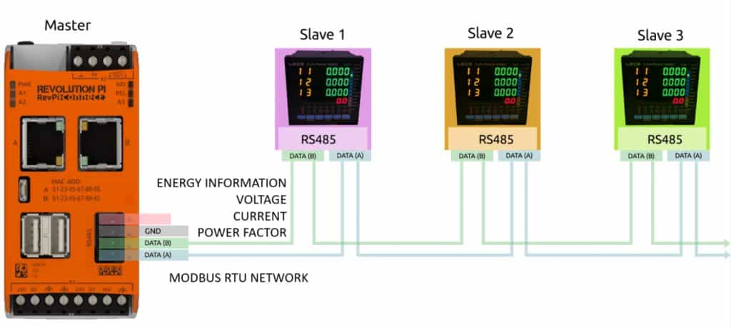
In this article, by connecting a controller module such as RevPi Core/Connect to a meter (LEOS AC3-MF1, a full-featured AC 3-item multifunction meter.), a controller module such as RevPi Core/Connect can be used to connect to the meter. The ports use RS-485 and RevPi's Modbus virtual master feature. In this case, the RevPi Connect will act as the Modbus master and the LEOS model AC3-MF1 will act as the Modbus slave.

▍預設配置,查看其他教學文章
1. Use RevPi to connect to all devices via remote SSH protocol.
2. Configure RevPi Core/RevPi Core 3 to start in GUI mode.
3. How to use remote desktop with RevPi Core/RevPi Core 3
ralph lauren outlet
- 1 PC
- 1 RevPi Connect
- 3 LEOS AC3-MF1
- 2 sets of 24V DC power supplies
ralph lauren polo ralph lauren outlet
1. The LEOS AC3-MF1 measures 3-phase power and can send measurements via Modbus RTU or RS-485. After powering up all devices, connect them according to the following diagram.
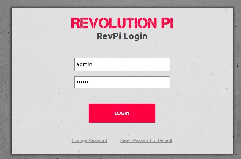
2. Open the Web Server page on your computer, enter the IP address of RevPi Connect, and follow the details below to log in.
- Username: admin;
- Password: Can be found on the side sticker of the RevPi device.
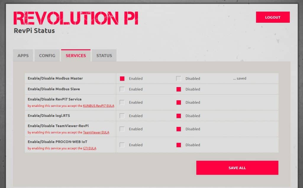
3. The web window of RevPi Connect device will appear, select Services option and click "Enabled Modbus Master", then click "SAVE ALL".
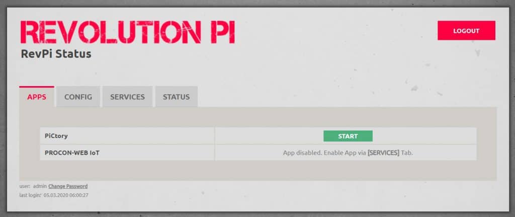
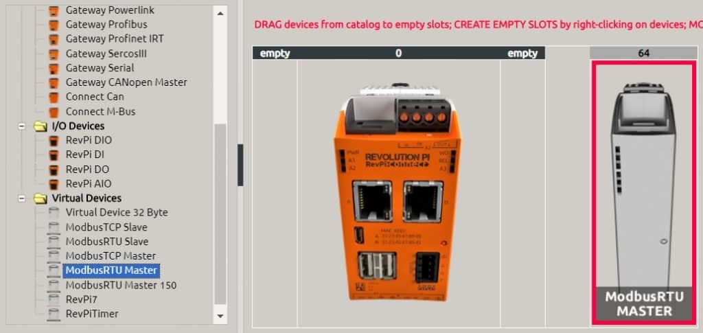
4. Select "APP" application menu and click "START" to start the PiCtory program.
5. Drag the Modbus RTU Master icon in the virtual device from the left catalog option and move it to one side of the RevPi Connect image (in the empty boxes on both sides).
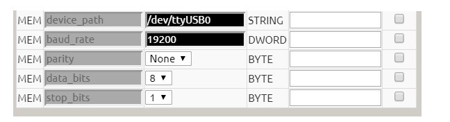
6. Configure the RS-485 interface of RevPi Connect to adapt to the LEOS AC3-MF1, as shown below
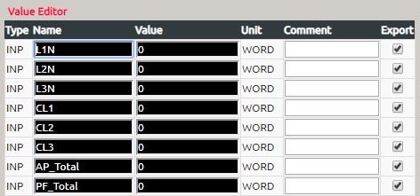
7. Since the user can configure MODBUS to read multiple values from the LEO AC3-MF1, the readings will be tested in detail in this example, as described below.
- Voltage lines 1 to 0
- Voltage lines 2 to 0
- Voltage Cord 3 to 0 lines
- +/- Phase current line 1
- +/- Phase current line 2
- +/- Phase current line 3
- +/- Total active power
- Total Power Factor
Therefore, the value editor for Modbus RTU Master has been added, i.e. the name in the following picture.
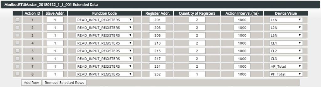
8. Right-click the added Modbus RTU Master image and select the Extended Data directory. the Extended Data for the Modbus RTU Master will appear. the Modbus RTU Master is configured as before as shown below.
Then follow the steps below to save the values.
- Select Directory File → Save As
- Select the directory file → Save As to start the configuration.
- Select the directory File → Load Start-Config.
- Select Catalog Tools → Remake Drivers and click the OK button
9. Run the PuTTY program from your computer or open the terminal program on RevPi Connect and enter the following commands. Test the LEOS AC3-MF1 reading via MODBUS RTU.
- piTest - 1- r L1N
- piTest - 1- r CL1
- piTest - 1- r AP_Total
- piTest - 1- r PF_Total
10. Select Directory File and Export to create an offset list file that will reference the location of addresses in the Python program by selecting it as the offset list mode (template e02.json).
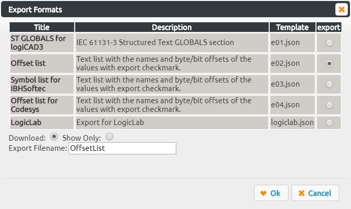
The result of this getting OffsetList.txt file is listed below.
- L1N 11 // Word
- L2N 13 // Word
- L3N 15 // Word
- CL1 17 // Word
- CL2 19 // Word
- CL3 21 // Word
- AP_Total 23 //WORD
- PF_Total 25 //WORD
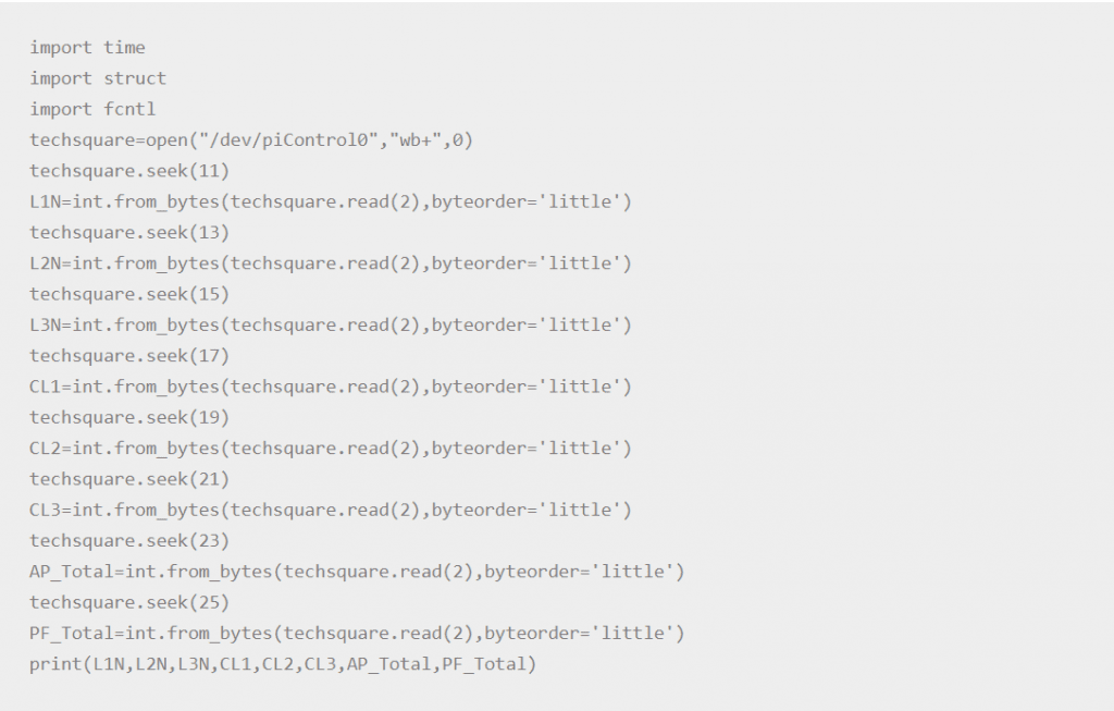
L1N Indicates the voltage between line 1 and neutral.
L2N indicates the voltage between line 2 and neutral.
L3N indicates the voltage between line 3 and neutral.
CL1 indicates current in phase 1
CL2 indicates current in phase 2
CL3 indicates current in phase 3
AP_Total indicates the total active power
PF_Total represents the total power factor.
11. Visit RevPi Connect using VNC Viewer and run Python 3 (IDLE).
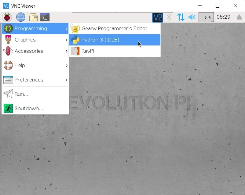
12. Enter the following commands to test all readings.
After completing the above steps, you will be able to see that L1N, L2N, L3N, CL1, CL2, CL3, AP_Total and PF_Total are output correctly.
***Note: If a new port is changed and the reading is 0 or does not work, restart the RevPi device to test again.