By Steve Smith | Pico Technology
Diagnostic Overview:
I don't know if this has happened to you, but there have been many times when I've been intimidated by a highly technical car, and it's a sign that what I'm going to do next is likely to fail. Happily, the more technical a car is, the more opportunities there are to learn from it when it breaks down. There is such a car right now, and the problem is that it has repeated failures due to overvoltage.
In an effort to break away from the usual case studies, I identified the cause of the customer complaint, which I'm pretty sure was an intermittent alternator failure, and it's been proven, so it's no surprise that you can choose not to read any further. However, when faced with an intermittent failure of a high tech vehicle, it is important to emphasize that the problem we are facing is the real reason for this case study (both in the parts market and at the franchised dealership).
Installing an AC generator is very easy and achieves the results we are looking for, but with the ability to characterize and operate the vehicle's power system using PicoScope and the technical data, we are able to demonstrate to our customers that installing an AC generator is necessary.
- Remember, if we don't understand how a system functions, then we won't be able to make a diagnosis of that system!
Failure phenomenon:
A BMW E60 545i with an N62 engine showed no signs of the instrument light coming on and the engine accelerated weakly.
Diagnostic process:
In retrospect, an over-voltage failure would have been indicated by signs such as: headlights brighter than usual, blower boost, increased windshield wiper speed, bulbs repeatedly going on and off, and lower electrolyte levels in the batteries (accompanied by a horrible sulfur smell).
None of these symptoms have been seen in any of our case vehicles. Here are mostly the symptoms reported by our customers: the vehicle drives without any problems, and then, without warning, the instrument panel lights up like a Christmas tree, and the warning message changes from “Brake Stability Help” to “Active Steering System Failure”, followed by mechanical symptoms such as the automatic transmission is in a particular gear (locking gears) and does not respond to the input of the gas pedal. Secondly, there are mechanical symptoms, such as the automatic transmission being in a particular gear (locked) and not responding to the input of the gas pedal.
For one thing, our client took a long time to get his car up and running in an airport parking lot. After driving about 6 kilometers into congested highway traffic, the symptoms mentioned above indicated that the client's car was in an unstable condition. During this incident, the client kept turning on and off the engine, and repeatedly tried to start the engine (the engine and starter motor were not responding, but the gauges were lit up).
After the vehicle was turned off for 5 minutes, it was able to start again without any recurrence of symptoms while the customer was driving the vehicle. ........ This has been going on for more than two weeks.
As always, communication with the customer is very important as the above information is necessary in our diagnostic process. A basic check confirmed that there were no problems with the connections that we could see, no leakage from the major components, and that the wiring harness was correctly routed. The connected diagnostic computer (part of the diagnostic puzzle) confirmed that all 4 control modules were over-voltage, 2 control modules reflected voltage related problems, and the PCM also reflected intermittent alternator communication failures.
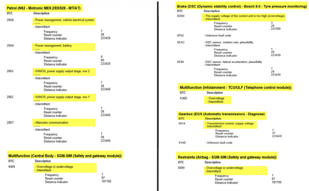
Diagnostic computers provide valuable information to explain the reasons for the appearance of warning lights and messages, and more importantly, how they correlate the historical sequence of events recorded through the “range tables” with each other.
- First report of voltage faults (1 per module) Central module and airbag module overvoltage condition report, code 181760
- Second report on voltage faults (3 occurrences) Overvoltage report for dynamic stability control module, code 222380
- Third report of voltage failure (1 occurrence) Overvoltage report on automatic transmission module, code 223420
- Fourth report on voltage faults (7 occurrences) PCM report on voltage related issues, code 223430
- The problem represented by the final code may have triggered all previously stored codes for the PCM to report an “AC generator communication” fault at code 223440.
Here we were able to determine that the overvoltage faults had been detected repeatedly over a period of time, mostly in the last 20 counts of the range meter, ending with the appearance of the AC generator's communication fault code.
In order to start the power diagnosis related to system faults, we have to start with a battery evaluation, and here PicoDiagnostics is very suitable because the software includes not only a battery test, but also a starter motor and alternator test. (A quick and non-invasive test to evaluate the 3 main components).
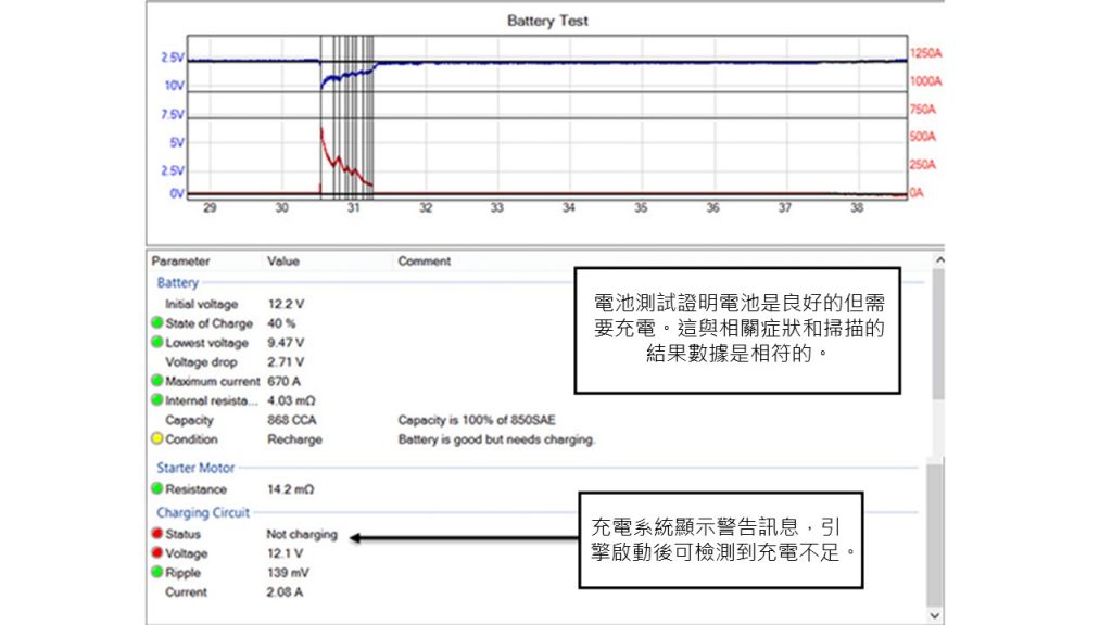
Here the test results were the same as expected for the initially low battery voltage (12.2V), and given the communication failures of the AC generator it was recommended that the battery be recharged. The test results also highlighted a potential charging problem where the battery charge appeared to be charging but at a very low efficiency.
At this point we need to know how the charging system on the vehicle works, and accurate technical information is key to familiarizing yourself with the system and diagnosing it (part of the diagnostic puzzle).
We have dealt with ordinary charging systems where the AC generator is indicated to be in operation by the charging indicator light (and internal voltage regulator), then we would have sufficient evidence to justify replacing the AC generator. However, this is a technologically advanced vehicle that utilizes a “power management system”, so care must be taken here.
Our AC generators are now part of a network that is controlled via a single communication line (BSD line - Bit Serial Data) via the power management software in the PCM. Based on inputs from battery temperature sensors and IBS (Intelligent Battery Sensors), along with engine and power load signals, the output of the AC generator can be utilized to achieve full control of the charging system in terms of battery life, fuel consumption and emission levels.

When there is for example an overvoltage condition during the detection process, we need to consider other components as well. Is it a fault in the PCM, is there a problem with the IBS, or is it a fault code in the network? It is better to ask these questions at the right time, rather than asking the same questions after the component has been installed and is failing.
Now the previous training and experience comes into play (part of the diagnostic puzzle) as we need to evaluate what we know and what we don't know. Now we are able to consider how best to minimize costs and ease of use in developing diagnostic protocols:
- Many modules are overvoltage, historically and currently - fact!
- Vehicle's battery is in good condition, but needs to be recharged - FACT!
- AC generators have intermittently lost their ability to communicate - FACT!
- Communication with the IBS (Intelligent Battery Sensor) is not lost - fact!
- AC generators need to be recharged to a certain level before they can be used after a fault - to be proven!
- The IBS module may send incorrect battery data - possibly
- The PCM control of the AC generator may be incorrect relative to the input - possibly
It is important to physically inspect the charging system with these considerations in mind. We will evaluate the charging control system and may indicate areas of concern.
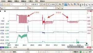
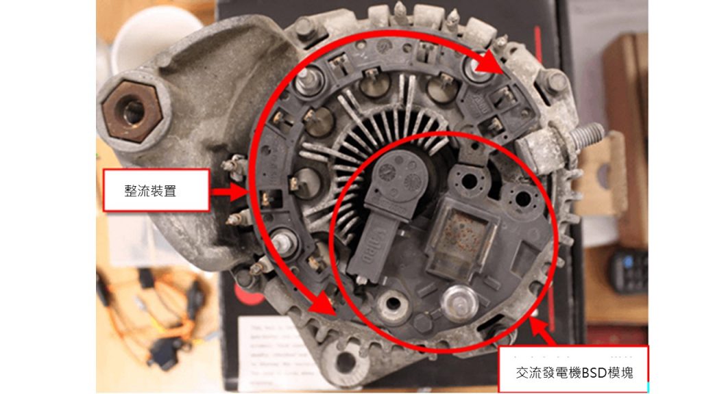
Using the PicoScope (the last part of the diagnostic puzzle) in the waveforms below you can see various aspects of the charging system and try to find the cause of the overvoltage fault. This includes an evaluation of the BSD AC generator control communication cables, output voltage, output current, and rectifier or phase windings.
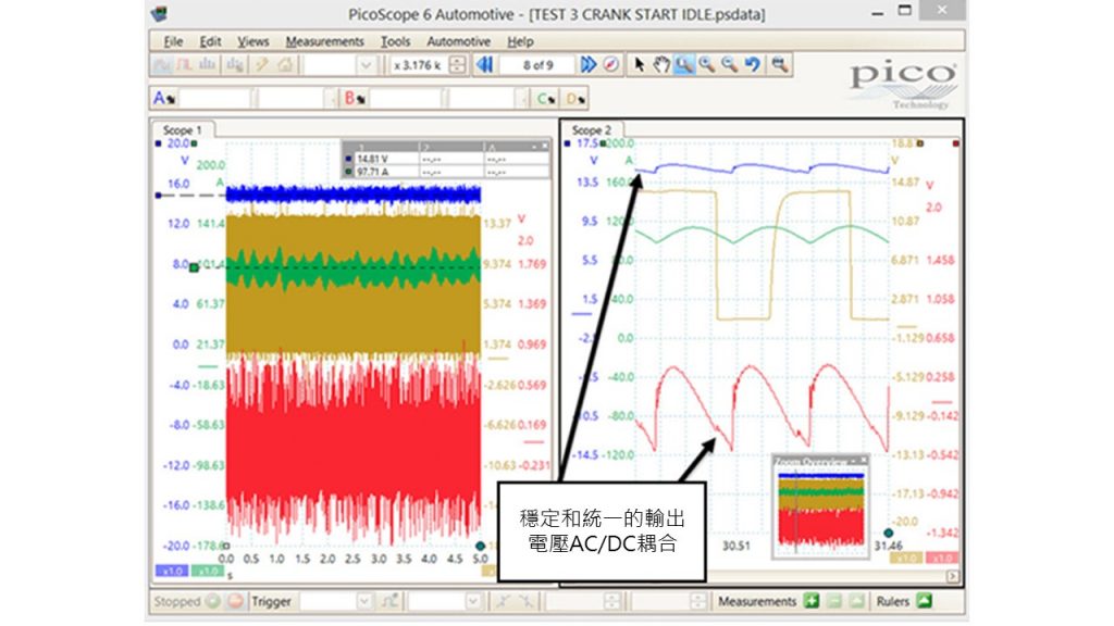
From the picture above we see a fast drop in the output current curve from 60 amps to -7amps, this is the most abnormal control part of the charging circuit and this affects the battery voltage. This is the most abnormal control part of the charging circuit and this affects the battery voltage. At the same time, we would like to have complete charging control and the battery voltage effect should be gradually prevented from producing undesirable side effects such as flickering lights. From the waveforms, the battery voltage at 15.34V seems to be getting some attention.
So can we capture the overvoltage condition and the operation of the PCM to shut down the charging system?
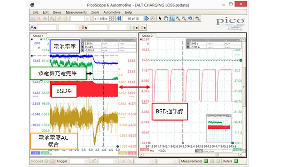
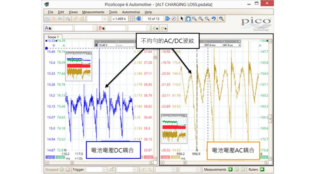
Scaling the waveforms corresponding to channels A and D (battery voltage, AC and DC coupling) we were able to evaluate the phase windings of an AC generator with a diode/rectifier. Also through the periodic peaks certain characteristics can be seen, the typical AC ripple from the expected output of the AC generator is not uniform and the battery voltage DC coupling also appears to be not uniform. This must indicate an internal AC generator component failure or wear and tear of the assembly responsible for charging the output, but it does not rule out the control system as the cause of the overvoltage.
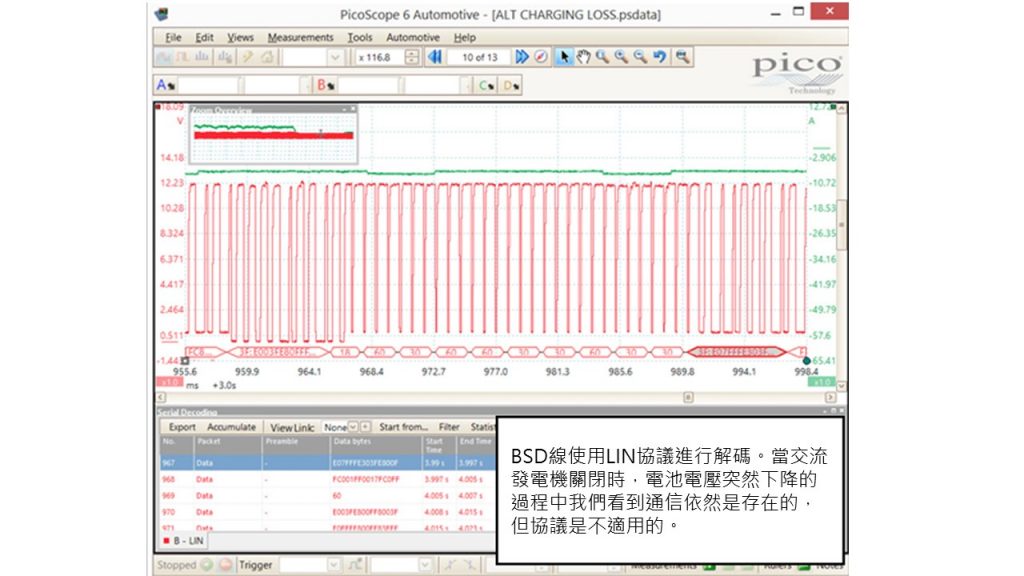
Knowing that the BSD line is responsible for the AC generator output (receiving commands from the PCM) the BSD waveform can be decoded using the PicoScope decoding function and attempting to identify faults using the decoded messages from the AC generator in the sudden shutdown (captured above) condition. Decoding the BSD line using the LIN protocol shows continuous communication between the AC generator and the PCM, as the PicoScope is able to decode the packets after the AC generator has been turned off.
Unfortunately, there is no way to convert the decoded data into something usable other than being able to prove that the communication exists.The BSD line provides special information for the BMW brand and makes the BUS voltage level the same as the LIN BUS voltage level, but the values decoded by the two are completely different.
In all tests on this point, we have demonstrated internal studies of the AC generator, but we could not definitively rule out PCM or IBS (items 6,7 of the diagnostic plan).
Our suggestion was to contact the local BMW dealership to ask if they had the equipment and use their diagnostic equipment to either decode the BSD lines or drive the alternator using the “Dynamic Test” function (where the decoder commands a high or low charging output by simulating the BSD lines to send a message). To my surprise, the dealer's decoder does not have this capability, so we are now all in the same position at this stage of the diagnosis.
Some tools on the market today are capable of simulating charge control commands such as BSD, LIN and PWM signals. They are used to perform AC generator evaluations, and these expensive tools are often purchased by repair dealers who realize the value of these tools during the repair process.
After a few hours of study I was able to get a valuable piece of information that simply proved that the AC generator was the source of the overvoltage. What happens if the BSD communication between the PCM and the alternator fails? Will the battery discharge and the car be damaged? The answer is: no!
Whether the BSD line between the PCM and the AC generator should be open or not, the AC generator has a “mechanically aware” control and monitors the internal charge output like a conventional mechanically aware device.
With this information in hand, the BSD cable was removed from the alternator and the battery voltage was monitored using the PicoScope via the OBD socket. Here we were able to record the battery voltage fluctuations over a longer period of time.
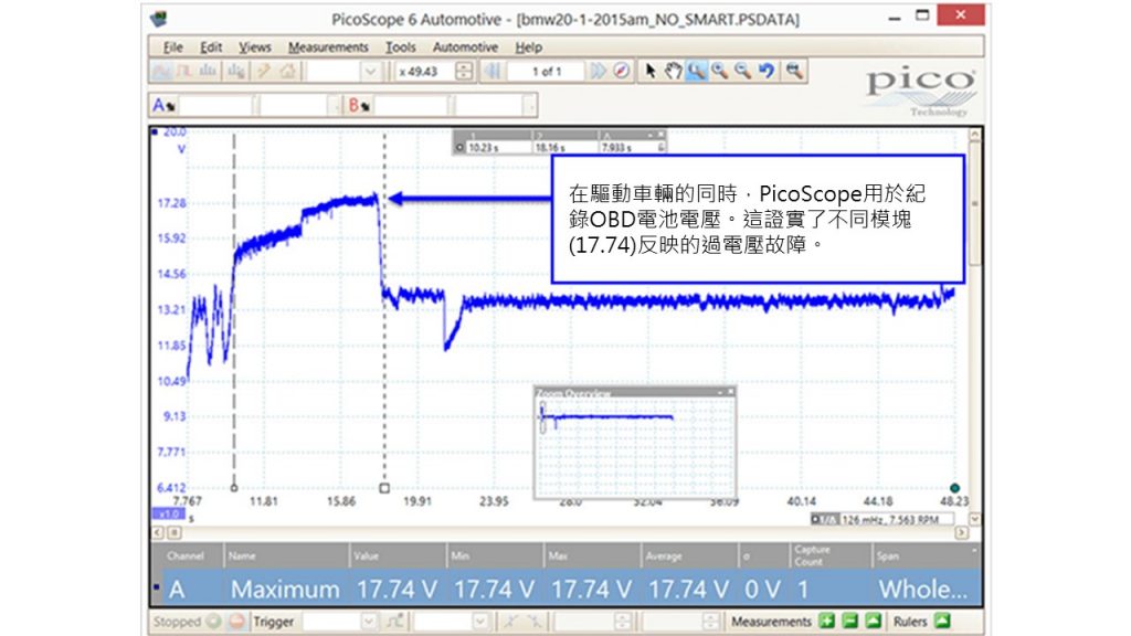
In the end, conclusive evidence proved that the over-voltage was caused by a failure of the generator's internal controls and not by the BSD control (over 17V could not be captured from the BSD line input). The BSD line is now removed and the AC generator is tested with confidence.
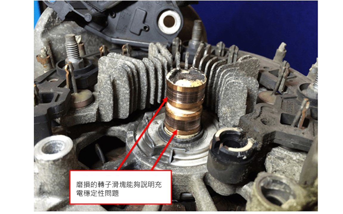
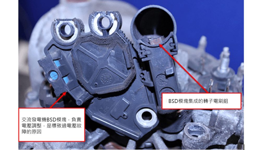
Further inspection of the AC generator showed no signs of overheating or burns, but heavy wear in the “slotted” areas as seen in the rotor slip rings. This condition could indicate a charging stability problem and result in an uneven pattern, which we were able to see in the case of an AC generator with AC coupled output voltage.
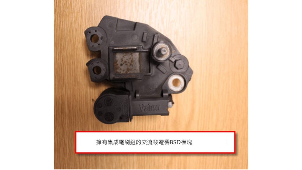
I have no doubt that the root cause of the overvoltage condition can be addressed by replacing the BSD module alone, but the labor required to remove and replace the AC generator and the wear and tear that occurs on the slip rings make replacing the generator the most effective means of repair for future reliability.
Diagnostic Conclusion:
The above waveforms demonstrate that a successful repair case requires a stable and uniform output voltage, regardless of AC or DC coupling (the battery voltage is stabilized at 14.81V).
This case study gave me a better understanding of the vulnerability of the input voltage operating module. The module's effect on the vehicle control system was dramatic, and the input voltage was not only too low but also too high. The alternator is a common component, so the diagnostic problems associated with it were not a concern. However, as technology continues to evolve, charging system control will become more complex and undoubtedly more efficient when integrated into the vehicle network.