preamble
The purpose of this article is to provide first-time users with an overview of the installation, configuration, and debugging of the X-gateway gateway. Through the step-by-step guide in this article, users can get the X-gateway gateway up and running normally and communicate with other devices in a basic way.
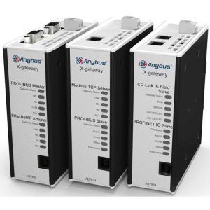
The main function of the Anybus X-gateway is to allow you to seamlessly and internally connect your PLC control system and connected devices between any Fieldbus/Industrial Ethernet network, quickly transferring cyclic I/O data between the two networks, so that your PLC does not need to perform additional computational work. In addition, the X-gateway can be configured via the USB port using the Windows-based application Anybus Configuration Manager software. The network interfaces on the gateway are usually configured from their respective networks using third-party configuration tools.
Solutions
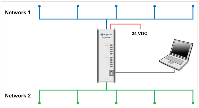
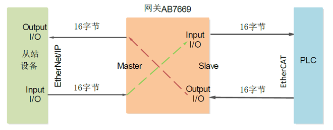
In this case, the AB7669-F gateway is used as an example. One side of the gateway is used as an EtherNet/IP master, and the other side is used as an EtherCAT slave, which can realize the integration of EtherNet/IP devices into EtherCAT networks. This article only introduces the configuration of the EtherNet/IP master side of the gateway and the gateway configuration process, the other side of the EtherCAT network and PLC configuration can be configured according to the actual configuration software used.
X-gateway Gateway Configuration Flow
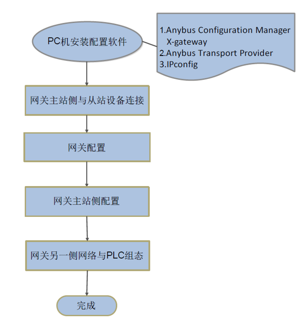
Software Installation
Install the necessary configuration software and drivers on your computer, which can be downloaded from the product page on the official website:
(1) Gateway Configuration Software: Anybus Configuration Manager X-gateway
(2) Driver: Anybus Transport Provider
(3) IP address configuration software: Ipconfig
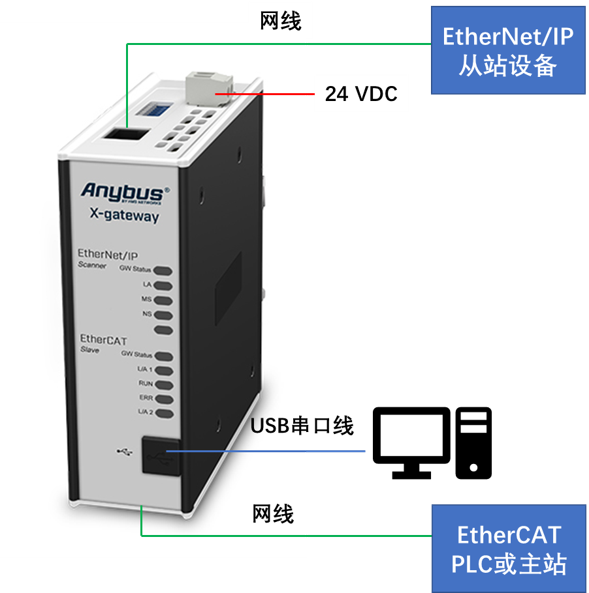
Hardware Connections
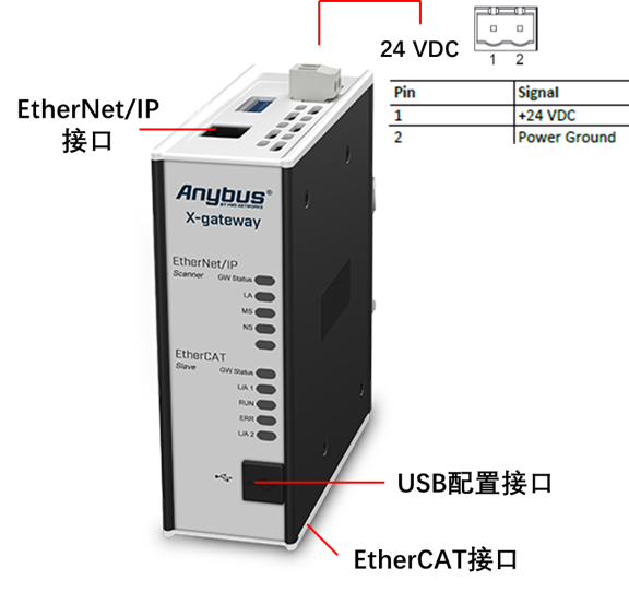
1. The AB7669 interface is defined as shown in the figure:
Gateway Configuration
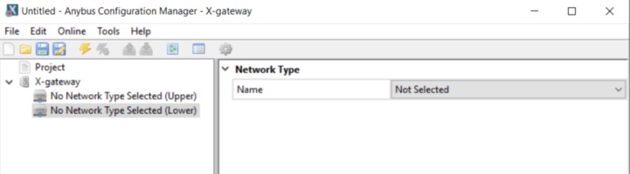
1. Connect the gateway and PC computer via USB serial cable, open Anybus Configuration Manager to configure the gateway. It is recommended to upload the configuration information of the gateway first during the configuration process, and then modify the parameter information such as the number of input/output bytes or the control status words according to the actual situation, so as to avoid the wrong selection of the network on both sides. Each Anybus X-gateway gateway is configured by default at the factory with 20 bytes of output and 20 bytes of input.
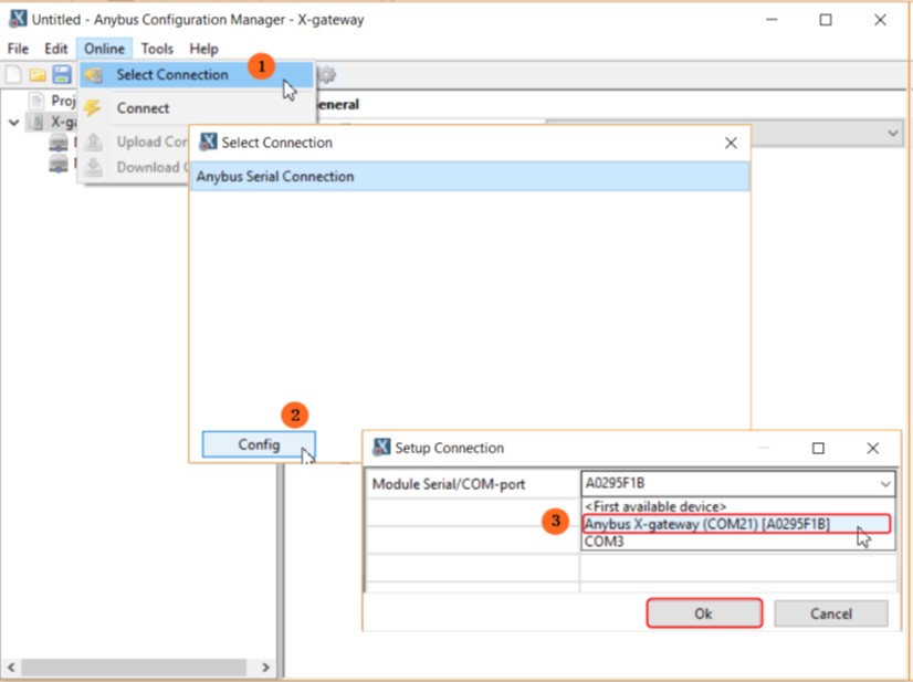
2. Select Connection Port: Click “Online” in the menu bar of the configuration tool interface, click “Select Connection” in the drop-down menu, and then click the “Config” button in the pop-up dialog box. Config“ button, in the pop-up dialog box, select ”Anybus X-gateway(COM21)[A0295F1B]“ option in the drop-down menu, and finally click ”OK" to confirm. Click "OK" to confirm.
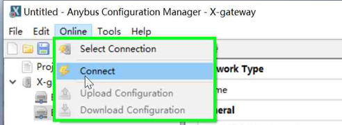
3. Connect: Select the toolbar shortcut or the Connect button in the Online menu bar to establish a connection. If the connection is established the Connect button will be grayed out and the Disconnect button next to it will be highlighted.
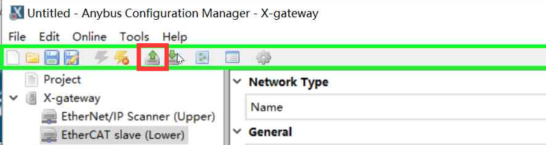
4. Upload Configuration Information: Click the Upload Configuration from Device button in the shortcut to upload the configuration information in the gateway, and then click the “Close” button in the progress bar when the upload is completed.
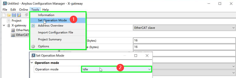
5. Click “Tools” in the menu bar and select “Set Operation Mode” option in the drop-down menu, in the pop-up dialog box, switch the gateway operation mode to “Idle” mode. In the pop-up dialog box, switch the gateway operation mode to "Idle" mode, the EtherNet/IP master needs to be in Idle mode when configuring.
Gateway EtherNet/IP Master Side Configuration
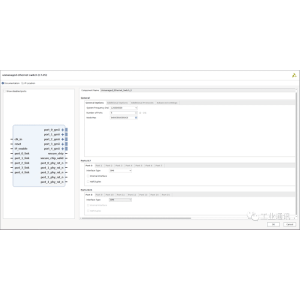
Configuration on the master side of the gateway is performed through a browser accessing the web interface.
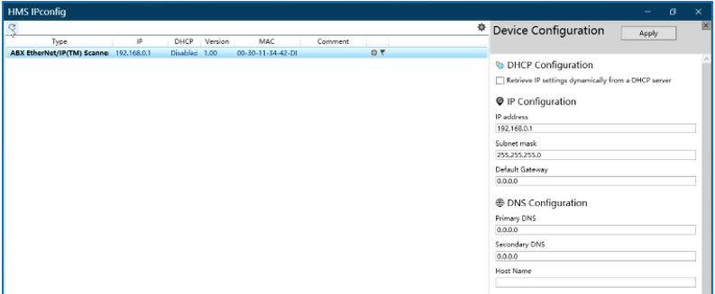
1. Use a network cable to connect the EtherNet/IP interface between the PC and the gateway AB7669. Open the IPConfig software, double-click the scanned network, and set the IP address of the gateway's EtherNet/IP network to be on the same network segment as the IP address of the PC in the pop-up dialog box.
2. Open the browser and input the IP address of AB7669 EtherNet/IP network port, which is the same as the IP address configured in the previous step, you can enter the EtherNet/IP master Web configuration interface.
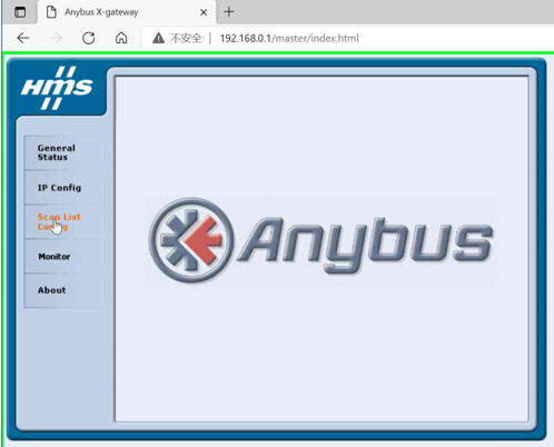
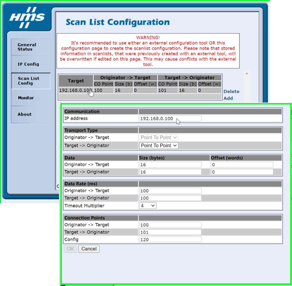
3. Click the “Scan List Config” button in the left list to add slave device information.
Click the “Add” button on the screen.
Enter the IP address of the EtherNet/IP slave device in the pop-up dialog box “IP address”.
In “Data”, input the number of input and output bytes from slave device (Originator -> Target: output, Target -> Originator: input) in bytes; in “Offset”, input the offset address of data storage, starting from 0. When there are multiple devices, the offset address needs to be calculated according to the number of input and output bytes of the previous device, the unit is word. In "Offset", enter the offset word, the offset address of the data storage, starting from 0. When there are multiple devices, the offset address needs to be calculated according to the number of input and output bytes of the previous device, the unit is word.
Fill in the “Connection Points” with the slave equipment manufacturer's example number to view its EDS file or contact the slave equipment manufacturer to obtain it.
Click “OK” to finish. Repeat the above operation if you have more than one slave device.
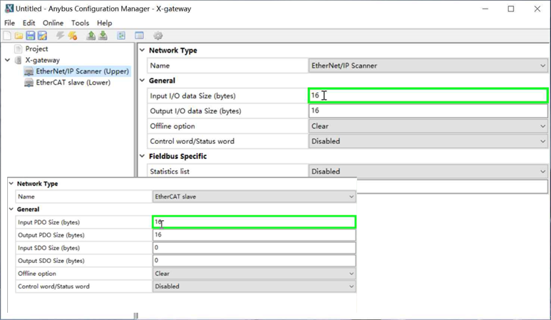
4. Switch to the Anubus Configuration Manager software and configure the data volume of both sides of the gateway, which is the same as the data volume in the previous step. The main purpose is to modify the number of input and output bytes, other parameters can be kept as default settings. Since the total input of the slave devices on the Ethernet/IP side is 16 bytes and the total output is 16 bytes, according to the working principle of the gateway, configure the input on the Ethernet/IP Scanner side to be 16 bytes and the output to be 16 bytes, and configure the input on the EtherCAT side to be 16 bytes and the output to be 16 bytes, and keep the other parameters in the default settings.
5. Click the Download button in the shortcut to download the configuration information to the gateway, and then click the Close button on the progress bar when finished.
Contact Us