Failure background

A 2019 Audi A6L with a 2.0T engine has accumulated about 90,000 kilometers. The owner reports that the engine stalls occasionally while driving, and the frequency of malfunction is high and affects driving safety.
Troubleshooting process
After fault detection, theA number of fuel system-related fault codes are stored in the engine control unit., including "P025A Fuel Module Actuation-Electrical Failure/Disconnection" and "P228C Fuel Pressure Regulator Out of Limits-Low Pressure" (shown in Figure 1).

Figure 1 - Engine Control Unit Fault Codes
Clear the fault code after the road test, driving for a period of time found that the vehicle power drop, acceleration is weak.Low pressure fuel system pressure reduced from 600 kPa to 100 kPaThe system was restored to normal after restarting and a potential fault in the low pressure fuel system was hypothesized.
Low Pressure Fuel System Inspection
Checking the low pressure fuel system circuit of the vehicle (see Figure 2), the fuel pump of the vehicle is a three-phase electric motor, and the fuel pump control module receives the signal from the engine control unit. PWM (Pulse Width Modulation) Control SignalThe fuel pressure is regulated by three-phase electrical control of the fuel pump speed.

Figure 2 - Low Pressure Fuel System Circuit Diagram
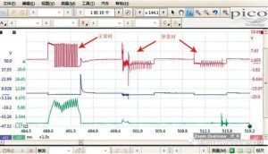
For further analysis, remove the rear seat and measure the voltage and current signals at fuel pump terminal 1 with a Pico automotive oscilloscope (see Figure 3).Discontinued anomalies。

Figure 3 - Fuel Pump Terminal 1 Voltage and Current Waveforms
Abnormal waveforms are displayed after amplification (see Figure 4).Voltage and current drop almost simultaneouslyMeasure the voltage and current signal waveforms at fuel pump terminals 2 and 3. Measure the voltage and current signal waveforms at fuel pump terminals 2 and 3, the anomalies are the same, indicating that the three-phase telecommunication signals of the fuel pump control module are interrupted occasionally, causing the fuel pump to fail to operate normally.

Figure 4 - Amplified display of abnormal waveforms
Further Inspection of Fuel Pump Control Modules
The fuel pump control module is located inside the right rear side panel of the vehicle, remove the panel and use the power test lamp to connect the fuel pump control module terminal T6ar/5 (power supply) and terminal T6ar/4 (iron), the test lamp lights up normally to rule out the fault of the power supply and iron circuit of the fuel pump control module.
Measurement of Fuel Pump Control Module Terminal T6ar/6 PWM Signal Voltage Waveform(See Fig. 5), it is found that the waveform is irregular and the minimum voltage cannot be reduced to 0 V but stays around 5 V. This phenomenon indicates that the PWM signal is unstable, which may be caused by a dummy connection or other connection problems. This phenomenon indicates that the PWM signal is unstable and may be caused by a dummy connection or other connection problems.

Figure 5 - PWM Signal Waveforms Measured at T6ar/6 Terminal
Signal Testing and Troubleshooting
Suspect that the supply voltage of the fuel pump control module is unstable, increase the oscilloscope 2 measurement channels, measure the waveforms of the supply and hitch signals of the fuel pump control module respectively (as shown in Fig. 6), and wiggle the wiring harness. When PWM signal voltage fluctuationWhen the power supply and iron signal waveforms do not change, exclude the possibility of a false connection in the power supply line.

Figure 6 - Fuel Pump Control Module Power Supply, Override and PWM Signal Waveforms
Disassemble the fuel pump control module wire connector and measure the signal voltage waveform at terminal T6ar/6 (see Figure 7).Stable waveforms and uniform voltage variations, troubleshooting the engine control unit.

Figure 7 - Signal Voltage Waveforms After Disconnection
The analysis shows thatPWM signal line is not connected.The signal cannot be pulled down from 12 V to 0 V when the fuel pump control module is connected. It is assumed that there is a malfunction in the control circuit between the engine control unit and the fuel pump control module.
Ultimate Cause of Failure
Measure the resistance between engine control unit terminal T91/9 and fuel pump control module terminal T6ar/6, the result is 28 Ω, indicating an abnormality. Peel off the fuel pump control module connection harness, and found that Damaged and corroded PWM control signal lines.(See Figure 8).

Figure 8 - Harness Damage Display
Troubleshooting and Repair
After repairing the wiring harness, remeasure PWM Signal Voltage Waveform(See Fig. 9), the waveform is uniform and regular, and the minimum voltage is stabilized at 0 V. After road test, the vehicle runs normally, and the fault is completely eliminated.

Figure 9 - PWM Signal Voltage Waveforms after Harness Repair
Fault Summary
This diagnosis centers onFalse connection of PWM signal line between fuel pump control module and engine control unitThe fuel pump control module does not receive the control signal properly due to the signal cable being disconnected. The fuel pump control module was unable to receive the control signals properly due to a false signal wire, which affected the normal operation of the fuel pump. This case shows that wire checking and signal integrity testing of the fuel pump control module is a critical step in solving similar problems, and emphasizes the importance of using a Pico oscilloscope for signal waveform detection.
During the diagnostic process, it was also found that the vehicle's fuel pump control module was unable to automatically enter emergency operation mode. When PWM signal line disconnectionThe engine control unit will continue to output 12 V when the engine control unit is on, further indicating that the engine control unit is realizing the PWM signal control through the iron signal.
Product Recommendation
")
Pico4425A 4-Channel Standard Package (EP032)
- Four-Channel High-Performance Automotive Oscilloscopes for Complex Diagnostic Needs
- Professional accessory packages for a wide range of test scenarios
- Quickly capture and analyze signals to improve diagnostic efficiency
- Ideal for automotive repair specialists and technicians