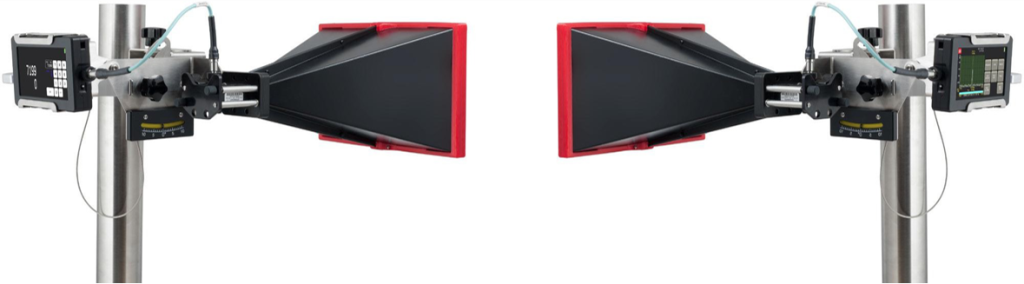
1 、 Video Distance Broadcasting:
Line-of-sight propagation (LOS propagation) refers to a propagation method in which radio waves are transmitted directly from the point of transmission to the point of reception (generally including the reflected waves from the ground) at a distance where the transmitting antenna and the receiving antenna can “see” each other. The distance of line-of-sight transmission is generally 20-50Km, and is mainly used in ultra-short-wave and microwave communications.
- Chinese name: 視距傳播
- Foreign name: line-of-sight propagation
- Abbreviation: LOS propagation
- Distance: 20~50Km
- Main applications: Ultra short wave and microwave communications
- Type I direct wave propagation
Short-wave communication, also known as high-frequency (HF) communication, is radio communication utilizing electromagnetic waves with a wavelength of 10-100m (frequency of 3-30MHz).
Microwave refers to electromagnetic waves with a frequency of 300MHz~300GHz (wavelength 1m~1mm). The ability of electromagnetic wave is related to its wavelength, the shorter the wavelength, the worse the ability. Due to the short wavelength of microwave, the weak ability to bypass, and not subject to the reflection of the atmosphere and the ionosphere, so the signal transmission is mainly utilized microwave in the line of sight within the distance of the linear propagation, also known as line-of-sight propagation.
2,Classification and Application of Video Distance Communication
Depending on the mode of transmission, video transmission can be categorized into the following 2 types:
The first type is direct wave propagation, in which radio waves radiated by a transmitting antenna travel in a straight line like light and are transmitted directly to the receiving point.
The second type is the earth reflected wave propagation, which is transmitted from the transmitting antenna and reflected by the ground to the receiving point.
Sight-distance transmission is a general term for the two modes of transmission mentioned above, and the waves received at the receiving point are generally a combination of direct and earth-reflected waves.
According to the different spatial positions of the receiving and transmitting ends, there are three general categories of sight distance transmission:
The first category refers to terrestrial video transmission, such as radio relay communications, television broadcasting, and terrestrial mobile communications;
The second category refers to line-of-sight transmission between ground and airborne targets such as airplanes and communication satellites;
The third category refers to line-of-sight communication between space communication systems, such as between airplanes and space vehicles.
3,Why is it important to verify that the microwave link has a clear line of sight?
1) Long-distance terrestrial microwave relay communication
There are two direct reasons for the use of relays for long-distance microwave communications on the ground: first, because theMicrowave wavelengths are short, have line-of-sight propagation properties, and the Earth's surface is spherically curved.If microwave communication is carried out on the ground, the antenna must be set up to a certain height, so that there is no physical obstruction between the transmitting antenna and the receiving antenna, and each other can “see each other” in the antenna height remains unchanged, when the communication distance is ultra-high a certain value, electromagnetic wave propagation will be blocked by the earth's own curved surfaces in order to carry out long-distance communication, it is necessary to use the relay method. In order to carry out long-distance communication, the method of relay should be adopted. Secondly, becauseMicrowave propagation is lossy, as the communication distance increases the signal fades.In order to extend the communication distance, it is necessary to receive and amplify the signals one segment at a time, and then send them to the next segment.
2)The Effect of Surface Obstructions on Microwave Distance-of-Sight Propagation
Ground obstacles such as hills, mountains, forests, and tall buildings are features that can block electromagnetic wave line-of-sight propagation. The effect of surface obstacles on microwave line-of-sight propagation is characterized by the introduction of blocking losses compared to free-space propagation.
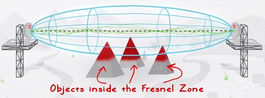
In free space, the electromagnetic energy radiated from the wave source T point to R point is mainly propagated through the first Fresnel zone, as long as the first Fresnel zone is not blocked, you can get the propagation conditions of the approximate free space. In order to improve the transmission directionality, microwave relay communication using parabolic antenna, which transmits the main energy concentrated in the first Fresnel zone, in order to ensure that the system for normal communication, receive and send antenna set up height to meet the obstacles between them as far as possible not to exceed the first Fresnel zone of the 20%, otherwise the electromagnetic wave multipath propagation will have an adverse effect on, resulting in a decline in the quality of communication, or even interruption.
A clear line of sight is critical to the performance of long distance microwave point-to-point links. It is important to ensure that the proposed link path has a clear line of sight and that nothing interferes with the signal. Any unforeseen performance problems can lead to new expenses and later result in necessary changes to the network topology. Even if a remote site appears to be visible, a wireless TV line can be affected by objects in the so-called Fresnel Zone, an elliptical area immediately adjacent to the visual link path, the width of which varies with link distance and channel. For example, if a hard object (such as a ridge or a building) is too close to the signal path, it may reduce the strength of the radio signal, and even if the obstacle is unobstructed, a direct line of sight to the planned receiving signal level cannot be achieved. Therefore, the necessary clearance in the Fresnel zone must be calculated and taken into account when designing the link path.